3.2.6:VREF setting
1:About VREF Output Jump
PowerWriter® products, when starting the process of connecting the target chip, if the connection to the target chip fails, including but not limited to no connection to the target chip, wiring errors, can not be recognized, etc., it will try to perform a POR (Power On Reset) power-on reset of the target chip, so the phenomenon in the output power supply will appear, the output (VEXT, VREF) power supply Charging and discharging behavior, there is a jump, so the purpose of processing can solve the following similar problems:
- If some chips are protected, not executing POR may result in not being able to connect to the target chip.
- If the debug port is disabled on some chips (including the reason of the program of the target chip), the execution of POR can precisely control the time control point of the connection request to ensure that it can be connected to the target chip, so as to carry out the operation of erasing and re-programming.
2:Setting method

Output power supply is optional:
- 1.8V :When 1.8V is selected, the IO signal output ports DIO/CLK, etc. are 1.8V.
- 3.3V(Default):When 3.3V is selected, the signal output ports DIO/CLK, etc. are 3.3V.
- 5.0V: When 5.0V (5V) is selected, the signal output ports DIO/CLK, etc. are 5.0V.
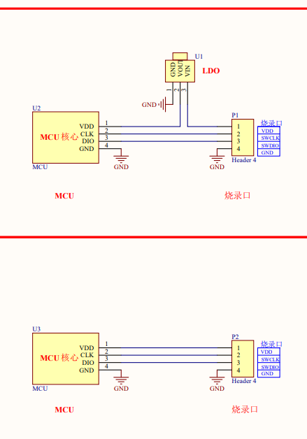
- External input:When an external reference is selected, the PowerWriter® needs to be externally supplied with a reference voltage in the range of 1.2V to 5.5V, while the PowerWriter® still needs to be powered by USB, and the external input is only supplied with the reference voltage.
3:Voltage switching
During debugging, the default output voltage is 3.3V. If you need to switch to other voltages, please set the target voltage through the PowerWriter® software, and then start debugging again to enter the set voltage:
In debugging mode, the system outputs 3.3V by default, if you need other voltages, please set and apply them manually through the client software.
4:Selection Recommendations
Refer to the chart below:
