3.1.4:Device Status
1.0 Overview
This chapter describes the normal or abnormal operating status of the hardware of the PowerWriter®, the definition of the status of the indicators, and the definition and functions of each power pin.The user can judge the working state of the equipment with the help of this summary. If the equipment is working abnormally, the description of this summary can judge and eliminate the anomaly.If it cannot be successfully eliminated by yourself, please reproduce the abnormal working state of the equipment, take a video and send it to our staff to help analyze and eliminate the anomaly.
1.1 Indicator description
1.1.1 PWLINK2,PWLINK2 Lite
According to the different states between the red and blue lights, the working state of the equipment is displayed:
- Red on: normal power on, red and blue alternately, a red light is on, indicating that the device is in standby state, at this time the chip is not recognized, no data interaction
- Alternating red and blue flashing: After normal power-on, the working status of the indicator indicates that the device has data interaction with the upper computer or the target chip, and the blinking frequency represents the busy degree of data interaction (if the data interaction reaches a certain degree, the phenomenon of alternating red and blue flashing will show a state of steady blue and occasional red, which is a normal phenomenon).
- Blue steady on: After normal power-on, if the blue light of the device is steady on, and no red/blue switch occurs, this is the abnormal working state of the device. Consider that there is device damage or abnormal working of the main control.
- No light on: After powering on, no light on. This phenomenon means that the entire device has no power supply. Please check the power supply status of the device or whether the circuit components are abnormal or damaged.
- Sudden shutdown: normal power-on, or normal operation, the indicator light (suddenly) out , considering the short circuit or the rear circuit with a large load and other circumstances to trigger the power failure protection of the device, please pay attention to check the short circuit or disconnect the rear circuit connected to the device, and re-power on to see whether the device can start normally.
1.1.2 PW200,PW300,PW400,PWX1
The above equipment has four indicators for only the working state of the equipment, which are:
Blue (excluding PWX1) : POWER indicator (POWER), normally should be on; If the device is off or blinking, the power supply is abnormal or unstable. Ensure that the power supply of the device is stable to ensure that the device can work properly.(PW200 OLED version has no blue power indicator light.)
Orange (yellow) : STATUS indicator, used to indicate the status of data interaction between the device and the upper computer or target chip. If no data is exchanged, it is in the off state. When there is data interaction, blinking occurs, and the blinking frequency represents the busy degree of data interaction (when a target chip is successfully recognized by the device or a large amount of data interaction is initiated, the blinking state may be characterized as steady on, which is a normal phenomenon).
Red : Operation error indicator (NG). This indicator will light up when an error occurs during this operation. It is extinguished (cleared) after the next operation.
Green : Operation success indicator (OK), when successfully completed an operation or programming, the indicator light will light up, indicating that the current operation is successful.The indicator light is extinguished (cleared) when the next operation is initiated, or when an error occurs.
Buzzer : (Except PWLINK system devices, other devices have buzzers.)
One sound : Only when the device is powered on normally, it is used to mark the normal startup of the device. The sound cannot be shielded.
Two rings : Used to indicate that the current operation has been successfully executed, usually accompanied by "OK" indicator light, can be set in the client mask.
Three rings : Used to indicate that the current operation has an error, usually accompanied by the "NG" indicator light, can be set on the client screen.
Long ring : The reason is that the device may detect a short circuit, pay attention to the upper computer prompt (if connected), and pay attention to the investigation
- tip
The PWX1 device has a screen display, and the power supply indicator is changed to orange, and the indicator status of the VREF pin is displayed.
1.2 Normal power-on status of the device
1.2.1 PWLINK2,PWLINK2 Lite
After the device is powered on, the indicator on the fuselage turns blue and then red. The status of the indicator depends on whether the device has data interaction Will show different phenomena.
1.2.2 PW200,PW300,PW400,PWX1
After power-on, four different color indicators light up at the same time, and with the buzzer "drop" after a sound, the blue light is on, the rest of the indicators After it is turned off, the three indicators except the blue light will have different phenomena according to the different working status of the equipment.
After the PWX1 device is successfully started, the device enters the system desktop.
1.3 Serial port self-test
When you find that the serial port is not working properly, you can short-circuit the RX, TX pins of the device, and then use a third-party serial port assistant to send any character, and check whether any character is received after each send, and whether the character received by the character is the same as that sent; If each sending is received and the sending is the same as the receiving, the serial port works properly. Or else The serial port is abnormal.
1.4 Device pin description
1.4.1 PWLINK2,PWLINK2 Lite
All equipment screen printing, in addition to PWLINK (a generation of products),
VDD: When pins 7 and 9 of PWLINK2 and PWLINK2 Lite are two VDD's, both VDD's output is 3.3V by default and can be set to 5V output or external input mode on the host computer. Examples of silk screen printing are as follows:
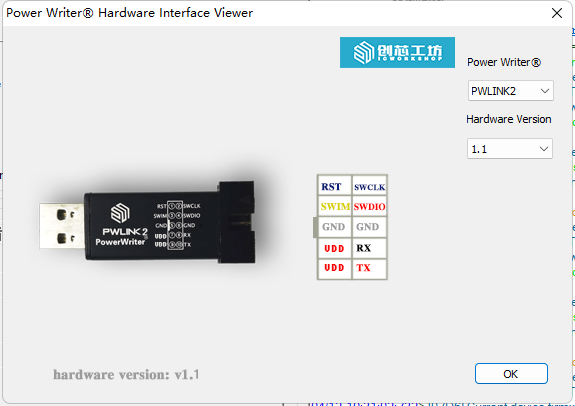
VREF 5V: When pins 7 and 9 of PWLINK2 and PWLINK2 Lite are VREF and 5V, the 5V pin only outputs 5V supply voltage, which is not controlled. The operating mode of the Vref pin can be configured by the upper computer, with 3.3V output by default, 5V output mode by the upper computer, or an "input mode" that provides an internal communication reference level. The communication level of sw pin is consistent with Vref. Examples of silk screen printing are as follows:
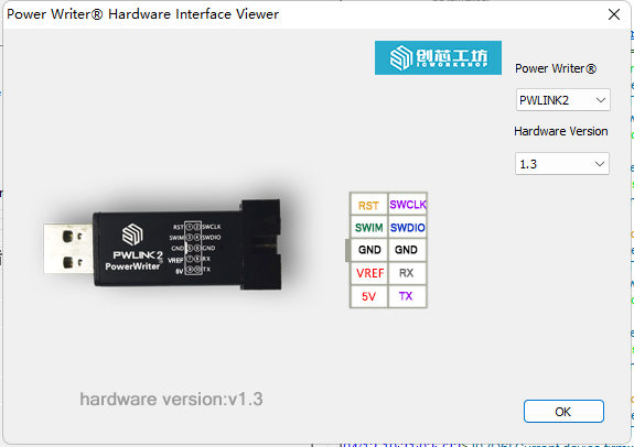
In the above two cases, how to modify the output voltage on the upper computer, see Interface level Setting
When the device is working normally, the Power On Reset (POR) policy is not executed, and no data is exchanged.
SWDIO : Normal high level (generally equal to VDD), the level size is affected by the upper computer Settings.
SWCLK : Normal low level (the above two pins may receive some special application scenarios to adjust, at present it is like this)
1.4.2 PW200,PW300,PW400,PWX1
Power pin VIN: Power input, input voltage support between 2.8V~6V, internal 5V regulated output as the working power supply of the device. The role of this pin is to power the entire programming device (not applicable to USB to Typd-C power supply). Therefore, if you use this pin to power the device, please ensure that the power of the power supply is sufficient and stable. VREF(reference voltage), VEXT(extended voltage) : It can have the upper computer configuration working state. When it is output, it can output 1.8V 3.3V 5V voltage according to the Settings of the upper computer. When it is input, it can input 1.8V~5.5V for internal communication level reference.
When the device is in normal working state, no POR(Power On Reset) policy is executed, and no data interaction is performed,
SWDIO : Normal high level (usually equal to VDD), the level size is affected by the host computer Settings.
SWCLK : Normal low (After connecting the PowerWriter software and selecting the target chip, the SWCLK pin will output a voltage level that follows VREF.)
1.5 Equipment inspection method
1.5.1 PWLINK2,PWLINK2 Lite
When the programmer is powered on, the blue light is always on or the red light is not on, or there is no reaction when it is powered on, it can be judged that there is a certain hardware problem in the programmer. The user needs to recall what operations were carried out before the equipment was abnormal (after feedback, the approximate reasons are as follows: connected to a high-power device, to the high-power device power supply; Voltage reverse; Wrong power line; Improper operation causes the main control to be programmed by the surge of the USB port or electrostatic breakdown; If a device is plugged in or unplugged during an upgrade, or if the power goes out halfway through)
When the state of the indicator light is not abnormal, the blue and red alternans will be carried out at the moment of power on, and then the red light is always on; When the chip is identified, the blue light is always on; When the chip is not identified, the red light is always on. If compared with other programmer, suspected that there is a hardware problem in the programmer, the multimeter can be used to measure the SWDIO voltage to the ground to rule out, when the host computer does not select any chip, the voltage of SWDIO should be consistent with the interface level set by the host computer, if not, there is a hardware problem, the specific device problem inside the device. Specific analysis is needed to know.
1.5.2 PW200,PW300,PW400
When there is an abnormal lighting condition of the indicator light in the use process, it is necessary to consider the wiring problem, especially the connection method of VDD. The correct wiring details should be connected to the programmer to check through the client. If the hardware is abnormal by measuring the pin, see the above description.
(Note: When the device is powered on normally, keil does not recognize the device, or the PowerWriter® client recognizes the two ports, this is an old firmware driver migration problem, not a hardware exception problem, see how to handle driver exceptions)
All the above problems can be avoided by standard operation. It is recommended that users familiarize themselves with simple hardware circuit knowledge before use.
1.5.3 PWX1
PWX1 equipment has a screen display. If there is a problem, most of the time, you can eliminate it by observing the state of the equipment. If necessary, please contact the after-sales service to return to the factory for inspection and maintenance.