3.3.6:Impedance matching
1:Introduce
Ordinary wiring is adequate for the transmission of low-frequency alternating current (AC) signals and sound signals; however, ordinary cables cannot be used to transmit currents in the radio frequency range or at higher frequencies, where currents change direction millions of times per second, and where the energy is easily radiated out of the cable in the form of electromagnetic waves, resulting in energy loss. RF currents are also prone to reflections back to the transmitting source at cable connections such as connectors and nodes. These reflections act as bottlenecks, preventing the signal power from reaching its destination.
Impedance Matching: Simply put, "Characteristic Impedance" equals "Load Impedance", a specific relationship between the load impedance and the internal impedance of the source during signal transmission. The relationship between the output impedance of a piece of equipment and the impedance of the connected load that should be satisfied in order to avoid a noticeable effect on the operating state of the equipment itself when the load is connected. For electronic equipment interconnections, such as signal source and amplifier, front stage and back stage, as long as the input impedance of the latter level is greater than the output impedance of the former level of more than 5-10 times, can be considered a good impedance match.
To match a group of lines, first of all the impedance value of the load point, divided by the value of the characteristic impedance of the transmission line to normalize (equal to 1 ), so that the entire line, the different parts, the impedance to maintain relative consistency, will reduce the signal reflection, excitation, emission of electromagnetic signals, resulting in energy loss and thus affecting the signal quality.
2:Impedance Matching on PowerWriter®
Power Writer's output signal network, different signals, such as SWCLK, SWDIO, TX, RX, JTAG, SPI and other signal ports, due to the equipment reserved for future upgrades, performance will be more and more high , with different predefined impedance matching resistors, the range of 39R ~ 200R between, the overall relative bias of small . In general, there is no need to do additional characteristic impedance matching on the application side, but in relatively complex production scenarios, users are still recommended to increase the impedance matching resistor in the programming port to normalize the signal.
In order to analyze the programming details of Power Writer's logic on the target chip, the following diagram is used as a demonstration.
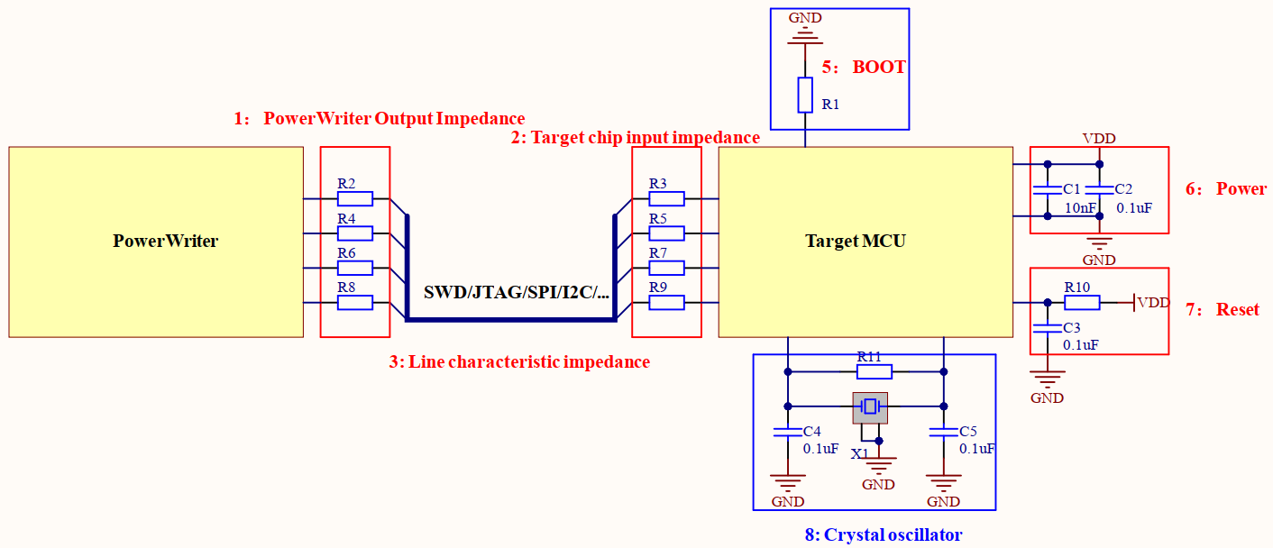
- The PowerWriter® outputs are designed with output impedances ,with different values for different circuits, in order to predict the impedance matching of the target chip and reduce the chance of signal reflection.
- The input impedance of the target chip is strongly recommended to include an impedance matching resistor in the programming port. The range can be adjusted according to the actual chip, and if possible, the matching resistor can be adjusted according to the measured signal quality.
- Characteristic impedance of the line, the line part of the description from the PowerWriter® device to the target chip between the connection of the communication cable, different lengths, specifications, the wire, will affect the characteristics of the impedance of the wire, so the choice of the appropriate communication cable, is still very critical.
PowerWriter® programming clock is high, so in the design of the PowerWriter® itself, the output impedance, the design is relatively small, in the use of higher speed programming on the target chip, it is strongly recommended that in the MCU programming input port, add the appropriate matching resistor, the range can be between 22R ~ 100R, specific to the actual prevail!
When programming the target chip using the Programming Socket Block, in addition to paying attention to the selection of communication wires and reasonable impedance matching, it is also necessary to pay attention to the integrity of the minimum system of the target chip.
- Power supply VDD, VDDIO plus a reasonable filter capacitor, such as 0.1uF + 10nF combination, can improve the stability of the power supply, reduce interference.
- POR RESET CIRCUIT: In case no reset pin is connected, the external MCU must have a power-on reset circuit in order to allow the target chip to perform a power-on reset.
- BOOT pin setting, BOOT pin setting, in some cases, is still important, refer to the design of the target chip.
- The XTAL external crystal, which is optional most of the time, is programmed with an internal RC oscillator circuit for programming the target chip.
2.1:PWX1 Optimized for Impedance
In order to allow the production equipment to have a more adaptable range of impedance, the PowerWriter® X1 comes with an adapter board that provides an additional, 0~100R adjustable impedance resistor, in addition to the output impedance of the X1 equipment, as shown in the figure below:
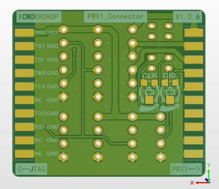
Adjustment range
- SWDIO:82R~182R,Default is 132R
- SWCLK:39R~139R,Default is 89R
3:Notice
- Try to avoid using spliced wires of different specifications as programming communication wires, which will result in inconsistent characteristic impedance during transmission, thus affecting the quality of the programmed signal.
- Wires are used as much as possible, parallel wires, twisted pairs, coaxial wires, ribbon wires, microstrip wires, and so on.
- The wire is not easy to be too long, too long wire, will amplify the signal loss, reduce the quality of the signal, caused by the increase in the defective rate.