3.4.6.1: Auto chips HSM
1: Tips
Power Writer support for the HSM function of the AC784x or AC780x security chip only enables the offline mode, meaning it is not possible to connect the programmer and the chip using the PowerWriter client software for real-time operations. Before configuring the PowerWriter HSM plugin, one needs to be proficient in the usage process and parameter configuration methods of the official development verification software ATC link tools from Auto chips. PowerWriter has reorganized the official software process and logical relationships for the offline function support of the HSM function, and the interface is more concise.
The configuration property names of the Power Writer HSM plugin are basically the same as those of the official tool ATC Link Tools. Therefore, this document will not list the corresponding relationships of each parameter one by one.
2:Entry
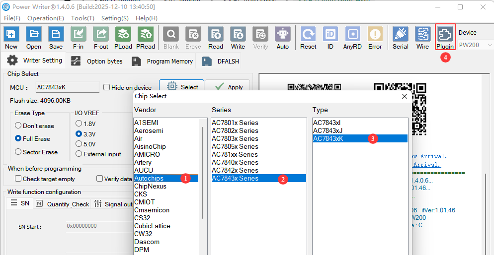
After selecting the Auto Chips AC784x chip, you will see the ![]() button in the toolbar. This function interface is the configuration entry for the HSM offline programming plugin of the Auto chips AC784x chip, as shown in the following figure:
button in the toolbar. This function interface is the configuration entry for the HSM offline programming plugin of the Auto chips AC784x chip, as shown in the following figure:
3:AC7843x HSM Configure
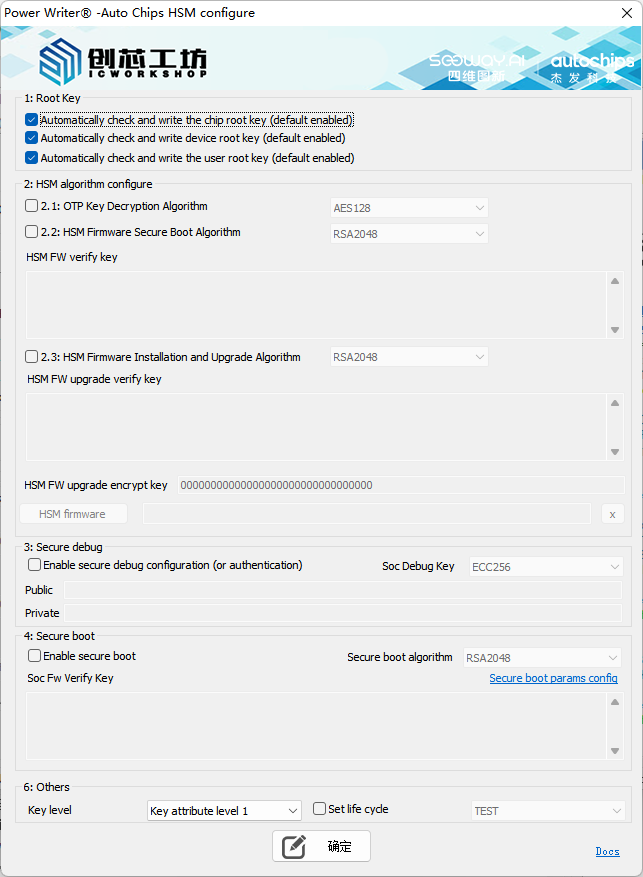
3.1:Root key

Before configuring HSM, the root key usually needs to be configured first. The PowerWriter automatically enables the function of configuring the root key. Please check or adjust it according to the actual application scenario.
3.2:HSM algorithm configure
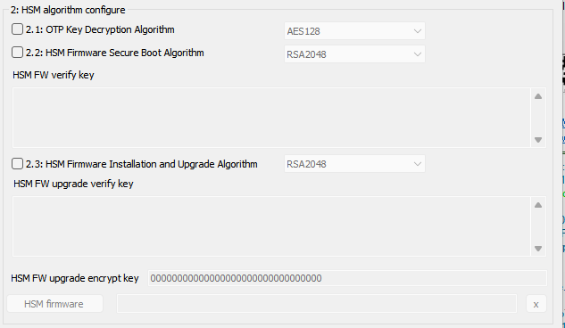
- OTP Key Decryption Algorithm: Sets the encryption and decryption algorithm for the HSM key (certificate) data. You can choose one of the following options:
- AES128: Set to the AES128-CBC encryption and decryption algorithm.
- SM4: Set to the SM4 encryption and decryption algorithm.
- HSM Firmware Secure Boot Algorithm: Set the verification algorithm for the secure boot of the HSM firmware. It can be set to one of the following options:
- RSA2048 (asymmetric): The public key (E(64) + N(256) = 320 bytes) is input through the interface.
- SM2 (Asymmetric): Enter the public key on the interface (64 bytes. The first byte indicates the compression format. If the key is 65 bytes long, please remove the first byte before filling in).
- AES128_CMAC (Symmetric): The interface accepts the original password as input, with a length of 16 bytes.
- SM4_CMAC (Symmetric): The original password is input through the interface, with a length of 16 bytes.
- HSM FW verification key: Sets the verification algorithm for the HSM firmware during startup. The data length is specified in the HSM firmware secure startup algorithm configuration.
- HSM Firmware Installation and Upgrade Algorithm: Set the verification algorithm for HSM firmware installation or upgrade. The type and format of the algorithm are the same as those for the HSM firmware secure boot algorithm settings. Therefore, no further explanation is provided here.
- HSM FW upgrade encryption key: Sets the data encryption and decryption algorithm for HSM firmware installation or upgrade. The length is 16 bytes and must comply with the following rules:
- The encryption algorithm corresponding to the RSA signature algorithm is AES128-CBC.
- The encryption algorithm corresponding to the SM2 signature algorithm is SM4-CBC.
- The encryption algorithm corresponding to the signature AES128-CMAC is AES128-CBC.
- The encryption algorithm corresponding to the signature SM4-CMAC is SM4-CBC.
- HSM Firmware: Includes the necessary HSM security firmware required for installation or upgrade.
- X: When the x button is clicked, the imported HSM firmware can be cleared.
3.3:Secure debug
HSM supports the setting of debugging access permissions, and can configure the debugging access authentication function of the chip, as well as the secure debugging configuration. It supports configuration and authentication. The configuration interface is as follows:

Enable Security Debugging Configuration (or Authentication): Turn on the configuration or authentication switch.
Soc Debug Key: Set the algorithm type used for secure debugging. The following types of algorithms are supported:
- ECC256: Configured as the ECC signature verification algorithm.
- SM2: Set to SM2 signature verification algorithm.
Public Key: Set the public key required for configuring secure debugging. The length should be 64 bytes.
tipThe public key is used in both the configuration process and the authentication process. If the public key is left blank, even if the interface is configured to be enabled, the functions of the current module will be disabled.
Private Key: Set the private key required for the authentication security debugging. The length should be 32 bytes.
cautionWhen reprogramming a chip that has enabled the security debugging function, a private key must be provided; otherwise, authentication cannot be performed, resulting in failure to access the chip and thus programming failure. When the chip does not have security debugging enabled, this setting can be left blank, indicating that no authentication is required.
3.4:Soc secure boot
Soc Security Boot refers to the security boot verification function of the Soc firmware, which is used to check whether the firmware has been modified. This firmware is not the HSM firmware, but rather the user firmware. The configuration interface is as follows:

Enable Secure Boot: Enable the secure boot configuration function of the SOC firmware.
Security Startup Algorithm: The configuration method is the same as that of the HSM verification algorithm, as described in HSM FW verify key.
Soc FW Verify Key:配置方法同 HSM 校验算法,见 HSM FW verify key。
tipAlthough the methods for configuring SOC secure boot and HSM secure boot are the same, they are not directly related and can be set independently.
3.4:Soc secure boot params
After enabling the SOC firmware secure boot function, it is necessary to check and set the secure boot parameters of the SOC firmware. If the parameters are not provided or the parameter settings are incorrect, when the programmer configures the target chip, it will result in the chip being unable to perform normal boot. The interface for configuring the secure boot parameters is as follows:
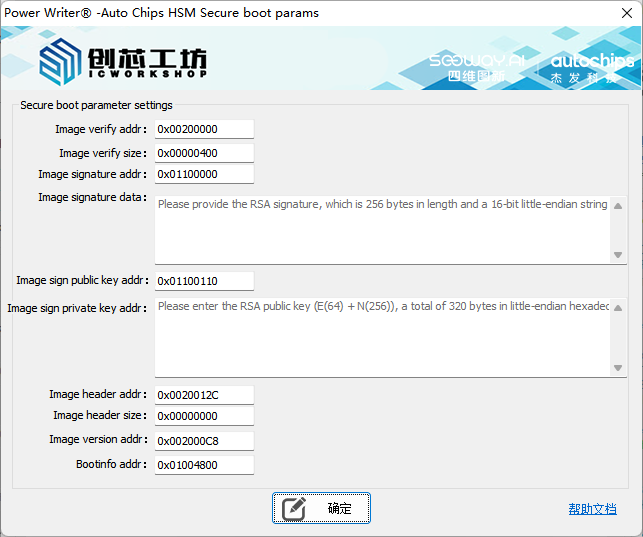
- Image verification address: Set the verification address information for the secure boot of the SoC. Please refer to the parameter settings of the ATC Link tool.
- Image verification size: Set the verification size for the secure boot of the SoC. Please refer to the parameter settings of the ATC Link tool.
- Image Signature Address: Set the signature data address for the secure boot of the SoC. Please refer to the parameter settings of the ATC Link tool.
- Image Signature Content: The signature data content for enabling Secure Boot in the SoC. Please refer to the parameter settings of the ATC Link tool.
- Image Signature Public Key Address: The storage address for the public key used for signing the SOC secure boot process. Please refer to the parameter settings of the ATC Link tool.
- Image Signature Public Key Content: The public key content used for signing the settings for Secure Boot on the SOC. Please refer to the parameter settings of the ATC Link tool.
- Image verification header address: Set the storage address for the verification header used in the secure boot of the SoC. Please refer to the parameter settings of the ATC Link tool.
- Image verification header size: Set the size of the verification header for the secure boot of the SoC. Please refer to the parameter settings of the ATC Link tool.
- Image verification version address: Set the storage address for the verification version of the Secure Boot of the SoC. Please refer to the parameter settings of the ATC Link tool.
- Boot info Address: Set the address for Boot info information of the Secure Boot of the SoC. Please refer to the parameter settings of the ATC Link tool.
After enabling the Soc secure boot, please make sure to check the secure boot parameter settings. Incorrect parameter configuration will prevent the target chip from booting.
3.5:Other
During the configuration process of HSM, the key levels of relevant certificates can be set. After completing all the product configurations, the product's life cycle can also be set for life cycle management, as shown below:

- Key level: When setting the HSM configuration, the key level is set to Level 1 by default.
- Set Lifecycle: Set the product's lifecycle. When this setting is enabled, PowerWriter will switch the product's lifecycle after completing all HSM configurations.
3.5.1:Clear or add user key
PowerWriter supports HSM functions, including the deletion and import of user keys, so that on the SOC side, the HSM's hardware encryption engine can be utilized for operations such as data encryption, decryption, generating MACs, verifying MACs, generating signatures, verifying signatures, etc. For the development documentation of HSM user keys, please refer to the official materials and DEMOs. This article does not provide specific descriptions. The interface for deleting and adding user keys is as follows:
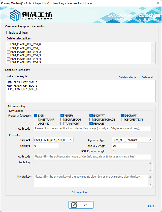
3.5.1.1:Clear user key
By using the "Clear Key" function, you can batch delete the existing key information. It supports deleting all keys or specific keys, which is equivalent to the API in the official SDK.
Hal_StatusType HSM_Hal_RemoveKey(HSM_KeyId KeyId);
3.5.1.2:Add user key
Structure of HSM Key Usages:
/* usage flag for EVITA key */
#define EVITA_KEY_USE_FLAG_SIGN                     0x1U
#define EVITA_KEY_USE_FLAG_VERIFY                   0x2U
#define EVITA_KEY_USE_FLAG_ENCRYPT                  0x4U
#define EVITA_KEY_USE_FLAG_DECRYPT                  0x8U
#define EVITA_KEY_USE_FLAG_TIMESTAMP                0x10U
#define EVITA_KEY_USE_FLAG_SECUREBOOT               0x20U
#define EVITA_KEY_USE_FLAG_SECURESTORAGE            0x40U
#define EVITA_KEY_USE_FLAG_KEYCREATION              0x80U
#define EVITA_KEY_USE_FLAG_UTCSYNC                  0x100U
#define EVITA_KEY_USE_FLAG_TRANSPORT                0x200U
#define EVITA_KEY_USE_FLAG_REMOVE                   0x400U
#define EVITA_KEY_USE_FLAG_DHKE                     0x80U

typedef struct
{
    /* Attributes of use flags, only the least significant 10 bits are valid */
    ehsm_uint16_t use_flags;
    /* Attributes of trnsp flags, only the least significant 2 bits are valid */
    ehsm_uint8_t trnsp_flags;
    /* Attributes of auth flags */
    ehsm_uint32_t auth_flag;
    /* size of auth value */
    ehsm_uint8_t auth_size;
    /*if value is 0 means element has auth_value data else indicates auth_value data exist in other element,
    NOTE now this flag only use on OTP key*/
    ehsm_uint16_t auth_value_exist_flags;
    /* Auth data, only valid when auth_flags isn't 0 */
    ehsm_uint8_t auth_value[EHSM_EVITA_AUTH_VALUE_MAX_SIZE];
} ehsm_key_flags_element_st;

typedef struct
{
    ehsm_key_flags_element_st sign;
    ehsm_key_flags_element_st verify;
    ehsm_key_flags_element_st encrypt;
    ehsm_key_flags_element_st decrypt;
    ehsm_key_flags_element_st timestamp;
    ehsm_key_flags_element_st secureboot;
    ehsm_key_flags_element_st securestorage;
    ehsm_key_flags_element_st dhkey;
    ehsm_key_flags_element_st utcsync;
    ehsm_key_flags_element_st transport;
    ehsm_key_flags_element_st remove;
} ehsm_key_usages_st;
ehsm_key_flags_element_st::use_flags : the corresponding relationship is as follows:
- SIGN: EVITA_KEY_USE_FLAG_SIGN
- VERIFY:EVITA_KEY_USE_FLAG_VERIFY
- ENCRYPT:EVITA_KEY_USE_FLAG_ENCRYPT
- DECRYPT:EVITA_KEY_USE_FLAG_DECRYPT
- TIMESTRAMP:EVITA_KEY_USE_FLAG_TIMESTAMP
- SECUREBOOT:EVITA_KEY_USE_FLAG_SECUREBOOT
- SECURESTORAGE:EVITA_KEY_USE_FLAG_SECURESTORAGE
- KEYCREATION:EVITA_KEY_USE_FLAG_KEYCREATION
- UTCSYNC:EVITA_KEY_USE_FLAG_UTCSYNC
- TRANCSPORT:EVITA_KEY_USE_FLAG_TRANSPORT
- REMOVE:EVITA_KEY_USE_FLAG_REMOVE
- The "trnsp_flags" attribute of the "ehsm_key_flags_element_st" class is initially set to 0.
- The "auth_flag" attribute in the ehsm_key_flags_element_st class is fixed as "EVITA_AUTH_TYPE_PASSWD".
- ehsm_key_flags_element_st::auth_size and ehsm_key_flags_element_st::auth_value correspond to the authentication code in the Key usage info, typically 16 bytes in length, with a maximum of 32 bytes.
- ehsm_key_flags_element_st::auth_value_exist_flags defaults to 0.
HSM Plain Key Configuration Structure:
typedef struct
{
    HSM_GenKeyAlgo KeyAlgo; /**< Key generate algorithm */
    uint16 RandomKeySize; /**< Key size only when KeyAlgo = RANDOM be used */
    uint8 *PrivKey; /**< Pointer to the buffer, the private key store in buffer */
    uint32 PrivKeyLen; /**< Private key length */
    uint8 *PubKey; /**< Pointer to the buffer, the public key store in buffer */
    uint32 PubKeyLen; /**< Public key length */
    void *KeyUsages; /**< Key usages for attribute, e.g. enc/dec */
    uint8 KeyUsagesCnt; /**< Key usages size */
    uint8 *AuthValue; /**< Key authentication value */
    uint32 AuthValueSize; /**< Key authentication value size */
    uint32 ValidUtil; /**< Key valid time */
    uint16 ExtParam; /**< E param size only RSA key, default set 0 */
    HSM_KeyId KeyId; /**< Key ID according to key algorithm type */
} HSM_PlainKeyCfgType;
- Key ID: Key ID, corresponding to HSM_PlainKeyCfgType::KeyId.
- Algorithm Type: Encryption algorithm type, corresponding to HSM_PlainKeyCfgType::KeyAlgo.
- Validity Period: The validity period of the key, corresponding to HSM_PlainKeyCfgType::ValidUtil.
- Random Key Length: When the algorithm type is set to HSM_ALG_RANDOM, the length of the random key can be configured. This setting governs the generation and verification of user MACs, corresponding to HSM_PlainKeyCfgType::RandomKeySize.
- Random Key Length: When the algorithm type is set to RSA, you can configure the length of the RSA public key exponent parameter, corresponding to HSM_PlainKeyCfgType::ExtParam.
- Authentication Code: Corresponds to HSM_PlainKeyCfgType::AuthValue and AuthValueSize, where AuthValueSize is automatically calculated.
- Public Key: Public key information required for asymmetric algorithms, corresponding to HSM_PlainKeyCfgType::PubKey and PubKeyLen, where PubKeyLen is automatically calculated.
- Private Key: The private key information required for asymmetric algorithms, corresponding to HSM_PlainKeyCfgType::PrivKey and PrivKeyLen, where PrivKeyLen is automatically calculated.
PowerWriter does not enforce parameter corrections during parameter checks. When providing certificate information, please adhere to the HSM SDK API format to avoid unexpected issues.
4:7805x HSM Configuration
After selecting the AC7805X chip, an expansion menu will appear in the toolbar. Click the Plugin button to access the expansion features interface. This interface provides all HSM security options for the AC7805X chip, as shown below:
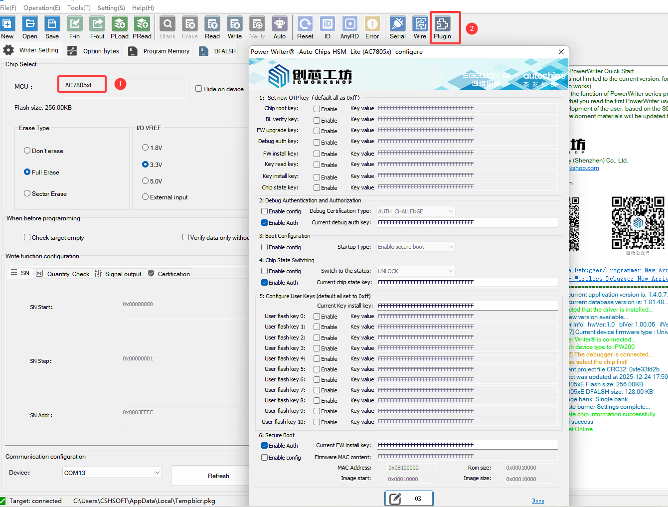
4.1:Set new OTP key
The OTP key stores the system keys required by the HSM module. Currently, these keys are OTP (One-Time Password) and can only be written once. The key types and functional descriptions are as follows:
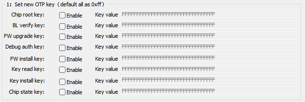
- Chip root key: User-defined, used for encryption, decryption, and MAC calculation.
- BL verify key: Used for verifying the bootloader.
- FW upgrade key: Used to verify the integrity of the upgrade package.
- Debug auth key: When Debug access authentication is enabled and the password mode is selected, the Debug Port is activated.
- FW install key: Used to enable erase/program permissions for the image area.
- Key read key: Used to enable read permissions for the user's Flash key.
- Key install key: Used to initiate write permissions for the user's Flash key.
- Chip state key: Used to enable write permissions for the chip's lock/unlock region.
To update the OTP key, check the Enable box for the corresponding key and enter a 16-byte key value. If the value exceeds 16 bytes, a warning will appear and the excess will be truncated. If the value is less than 16 bytes, it will be padded with zeros. The default value is all 0xff.
4.2:Debug Auth
The AC7805X chip supports two debug access authentication modes: AUTH_CHALLENGE and PASSWORD. When PASSWORD is selected as the authentication method, the authentication key is Debug auth key.
After the chip state switches to LOCK, connecting to the chip requires DEBUG authentication to establish a connection with the target chip.

Enable authentication functionality and keep it active whenever possible to minimize scenarios where the chip becomes inaccessible. Additionally, the current debug auth key represents the chip's real-time key during authentication. This key may be one of the following two possibilities:
- 16 bytes 0xff, indicating this is an empty chip that has not been configured.
- The previously configured debug auth key applies when the chip has previously utilized the new OTP key feature and configured the key following the debug auth key.
PowerWriter will prioritize using the user-provided key for debug access authentication. If authentication fails, it will attempt to use the chip's default value for authentication. If both attempts fail, it indicates that the provided key is incorrect.
4.3:Boot config
The AC7805X chip supports low-power standby mode wake-up bypass for secure boot. When secure boot mode is selected, it indicates that the secure boot function is enabled. When Standby mode is selected, it indicates that the secure boot process will be executed after waking up from standby mode, as shown below:

4.4:Chip State Switching
After the chip transitions from the unlock state to the lock state, access permissions for different memory regions can be enabled. Setting the lock does not require authentication. However, if the chip data state is configured after setting it to lock, authentication using the chip state key is required.

Enable authentication functionality and keep it active whenever possible to minimize scenarios where the chip becomes inaccessible. Additionally, the current chip state key represents the real-time key used during authentication. This key may fall into one of the following two categories:
- 16 bytes 0xff, indicating this is an empty chip that has not been configured.
- The last configured chip state key, when the chip previously utilized the new OTP key feature and configured the key after the chip state key.
PowerWriter will prioritize authentication using the key entered by the user. If authentication fails, it will attempt to authenticate using the chip's default value. If both attempts fail, it indicates that the entered key is incorrect.
If the current chip is in the lock state and debug access authentication is enabled and set to PASSWORD mode, debug access authentication must be performed during chip initialization. Ensure debug authentication is enabled, provide the correct key, and verify that chip state authentication is enabled with the key correctly entered.
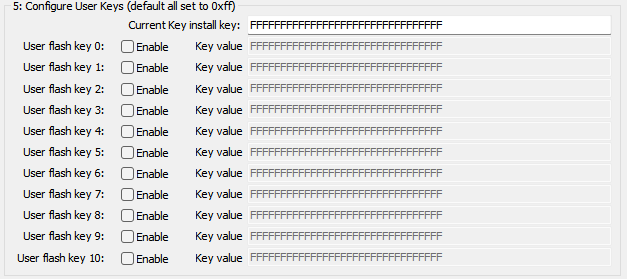
4.5:Configure Flash Key
The AC7805x chip supports configuring a user Flash key. The Flash key can function as a standard application key for data encryption/decryption, generating MACs, and performing MAC verification operations. The Flash key can be rewritten multiple times. Before writing a new Flash key, authentication must be performed using the Key install key. The interface is shown below:
Enable authentication functionality and keep it active whenever possible to minimize scenarios where the chip becomes inaccessible. Additionally, the current key install key represents the chip's real-time key during authentication. This key may be one of the following two possibilities:
- 16 bytes 0xff, indicating this is an empty chip that has not been configured.
- The last configured key install key was set when the chip previously utilized the new OTP key feature and configured the key following the key install key.
PowerWriter will prioritize authentication using the key entered by the user. If authentication fails, it will attempt to authenticate using the chip's default value. If both attempts fail, it indicates that the entered key is incorrect.
4.6:Secure boot
The AC7805x supports secure boot for user firmware. When secure boot is enabled, firmware undergoes integrity verification before execution. Programming firmware with secure boot enabled requires authentication using the FW install key during the programming process. The interface appears as follows:

When enabling secure boot, the following information must be configured. The HSM requires the following parameters to perform secure boot verification, as shown below:
- MAC Content: The 16-byte MAC content of the firmware calculated using the BL verify key. This content is used for firmware verification during Secure Boot execution.
- MAC Address: The storage address for MAC data used in firmware verification.
- ROM Size: The size of the firmware, which must be aligned to 0x1000.
- Image start: The starting address of the firmware, which must be aligned to 0x1000.
- Image size: The size of the firmware, which must be aligned to 0x1000.
Enable authentication functionality and keep it active whenever possible to minimize scenarios where the chip becomes inaccessible. Additionally, the current FW install key represents the chip's real-time key during authentication. This key may be one of the following two possibilities:
- 16 bytes 0xff, indicating this is an empty chip that has not been configured.
- The previously configured FW install key applies when the chip has previously utilized the new OTP key feature and configured the key following the FW install key.
PowerWriter will prioritize authentication using the key entered by the user. If authentication fails, it will attempt to authenticate using the chip's default value. If both attempts fail, it indicates that the entered key is incorrect.