3.1.22:Interface Board
PowerWriter provides PW200,PW300, PWX1 adapter boards.The adapter board introduces a large number of orderly interfaces, facilitating the pin confirmation and wiring during the burning process.
The high-voltage isolation adapter board is applicable to multiple products under Chuangxin Workshop, featuring an insulation isolation capacity of 5000V to ensure safety and signal integrity during the programming process.
1:Write Interface Board
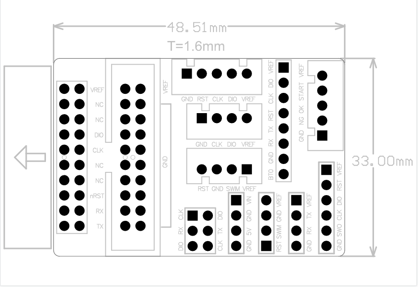
1.1 Interface Board Size
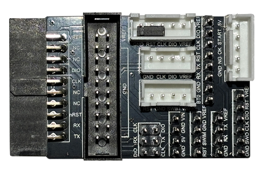
The PW200 or pw300 of the adapter board is shown below:
The PWX1 of the adapter board is shown below:
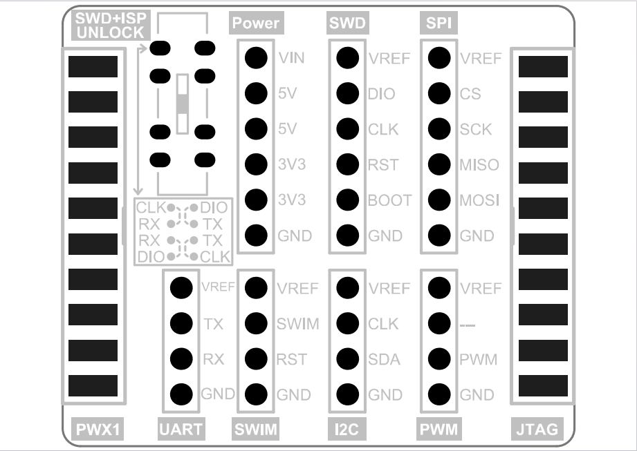
1.2 Interface Board Instructions
PW200/PW300 :The adapter board is used as shown below.
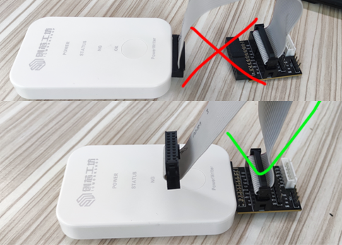
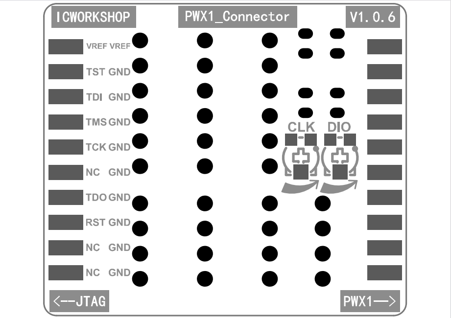
PWX1 :The adapter board is used as shown below.

Notes for the PWX1 adapter board:
In order to allow the production equipment to have a more adaptable range of impedance, the PowerWriter X1 comes with an adapter board that provides an additional, 0~100R adjustable impedance resistor, in addition to the output impedance of the X1 equipment, as shown in the figure below.For more information on impedance matching, please refer to this chapter.Impedance
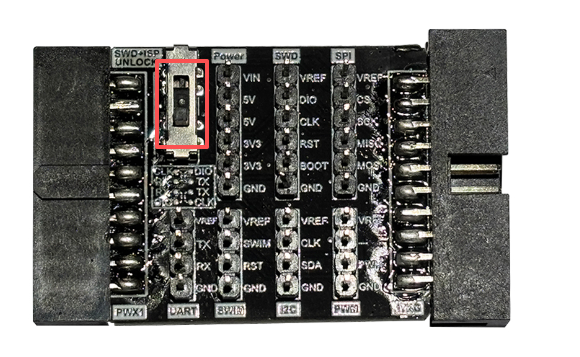
The red frame is for ISP unlocking. If there is no need for ISP unlocking, it will default to the middle position.
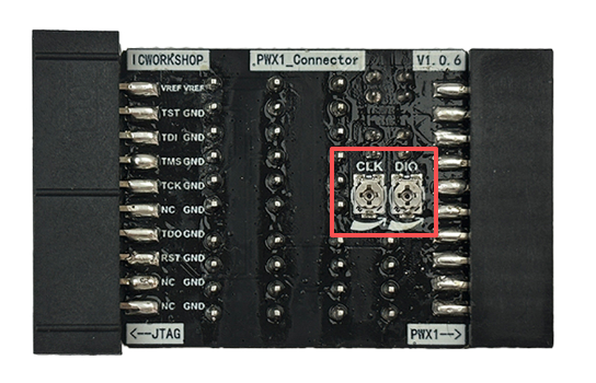
The red box indicates the resistance values of the resistors in series with SWDIO and SWCLK.
- Turn counterclockwise to decrease the resistance.
- Turn clockwise to increase the resistance.
- If communication is unstable or signal reflection is severe, increasing the resistance will help improve the situation.
2:Isolation adapter
2.1Basic Information
Insulation voltage:5000Vrms
Speed:150Mbps (MAX) / Debugging Clock > 10Mhz
Data latency:6.54us (typical values)
VREF Voltage Range:2.5V ~ 5.5V
Supported Devices:
Power Debugger
PW200
PW300
PW400
PWX1
The physical diagram is as follows:
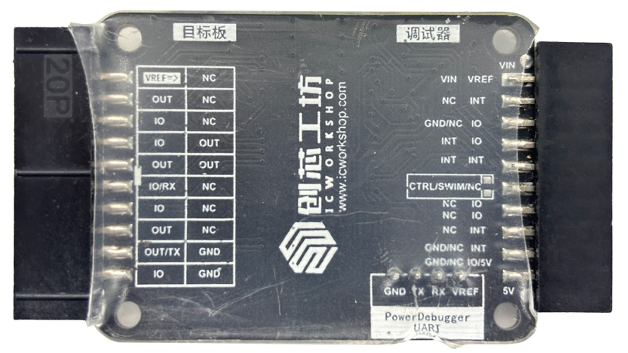
The silkscreen on the left indicates the communication direction of the port: IO can be used for both input and output; OUT is for output only.
PowerDebugger
Supported protocols: UART, SWJ, JTAG, wiring diagrams are referenced below:
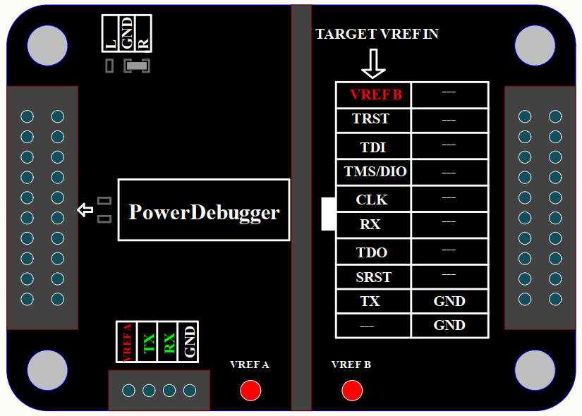
VREF B Requires power from the target board, voltage range 2.5V to 5.5V, Power Debugger IO voltage set to 3.3V or 5V, Serial port isolated, need to be accessed from the green independent 4PIN.
PW200/PW300
Supported protocols: UART, SWJ, SWIM, ITM(SWO), wiring diagrams are referenced below:
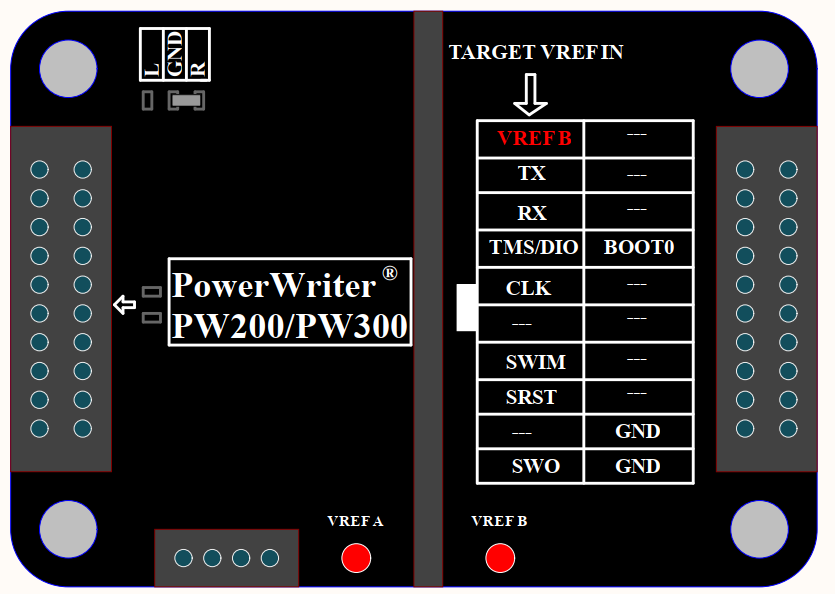
VREF B Requires power from the target board in the range of 2.5V to 5.5V, with the PowerWriter® IO voltage set to 3.3V or 5V (no external reference can be set).
PW400
Supported protocols: UART, JTAG, wiring diagrams are referenced below:
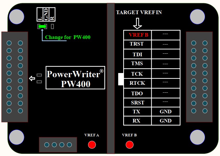
VREF B Requires power from the target board in the range of 2.5V to 5.5V, with the PowerWriter® IO voltage set to 3.3V or 5V (no external reference can be set).
GND to L needs to be adjusted (see Change for PW400).
PWX1
Supported protocols: UART, JTAG, SWJ, PWM, SWIM, wiring diagrams are referenced below:
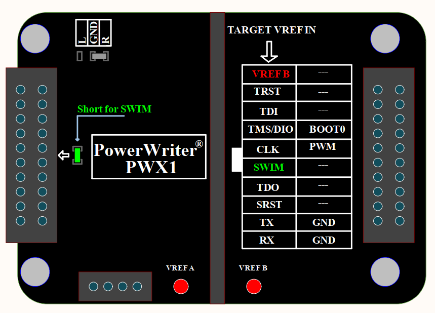
VREF B needs to be powered from the target board with a voltage range of 2.5V to 5.5V with the PowerWriter® VREF voltage set to 3.3V or 5V (no external reference can be set).
If you need to write STM8, you should short the green resistor bit as shown (see Short for SWIM).