3.1.18:Chip connect failure
1:Troubleshooting wire problems
Use a multimeter to self-test that the DuPont wire used is conducting.
- Connect the red and black pens correctly.
- Connect the red and black pens to the ends of the wires to be measured.
- If the resistance is close to zero, or relatively small, the wire is connected, and if the resistance is high the wire is disconnected.
If, after the above operation, you determine that there is a problem with the cable, you will need to replace the cable before proceeding with the operation.
2:Troubleshooting Hardware Issues
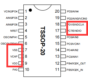
- First, open the corresponding datasheet of the chip to find the corresponding power supply pins and programming ports of the chip, and then make sure that the hardware is soldered properly and then connect the chip to the power supply.
- Without connecting the programming ports, such as SWDIO and SWDCLK, measure the voltage of SWDIO with a multimeter.
- If the chip is empty or there is no multiplexed SWDIO pin, the SWDIO pin has the same voltage as the power supply of the chip, if not, there is a hardware abnormality, please check the hardware.
Example references:

3:Troubleshooting programmer wiring problems
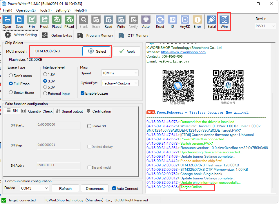
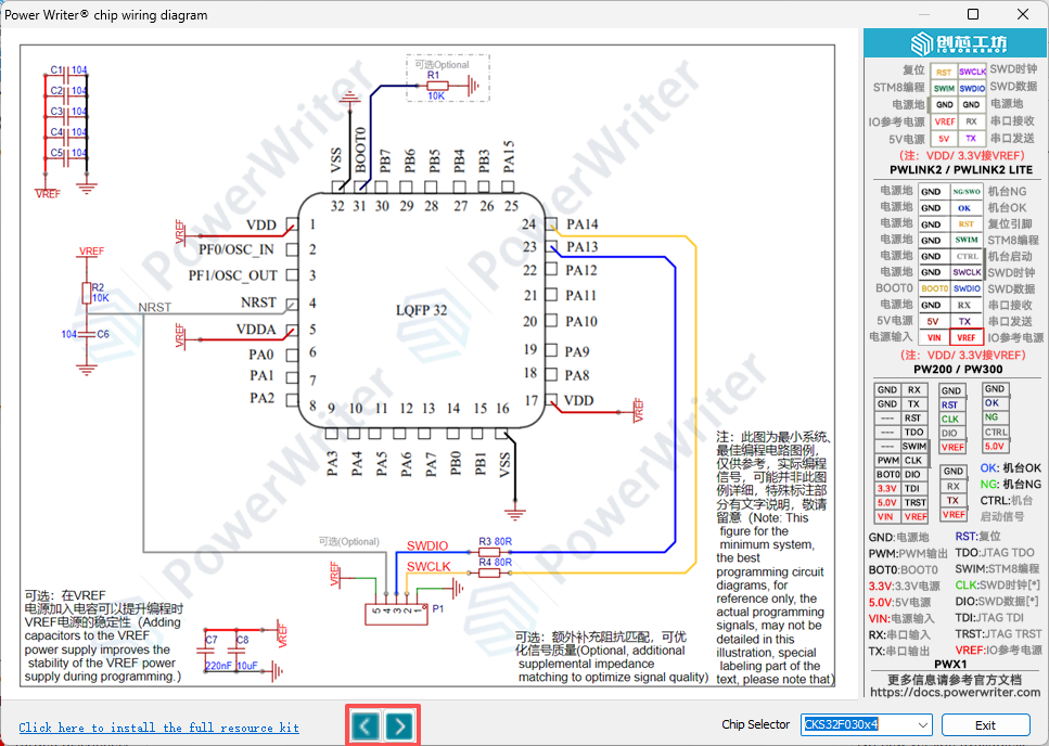
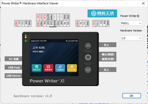
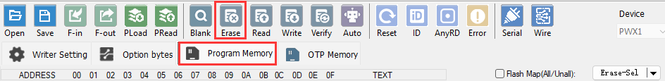
Open the PowerWriter® software and select the appropriate model number based on the chip model and view the appropriate connection diagram.
Click on the Tools button in the menu bar to view the interface definition for the corresponding programmer.
Prioritize the use of the connection cable provided with the programmer and ensure a stable connection.
Ensure that the corresponding power supply and programming port are connected properly. If they are connected properly, the software log will show that the target chip is connected.
For wiring details and description of the programmer pinout see About Wiring。
4:IO multiplexing pins
- When the program running on the chip has multiplexed pins, it is recommended to use only the programmer's power connector when connecting.
- When using an external power supply, connect the reset pins.
- When the chip is multiplexed, compilers such as KEIL may not be able to connect to the chip, so you need to use PowerWriter® software to erase the chip before debugging.
- When multiplexing the chip's programming pins in a program, it is recommended to add a delay of about 2~20ms before them.
5:Troubleshooting chip damage
- Replace the chip with a new one.
- Replace the PCB with a new one.
- Replace with another chip model.
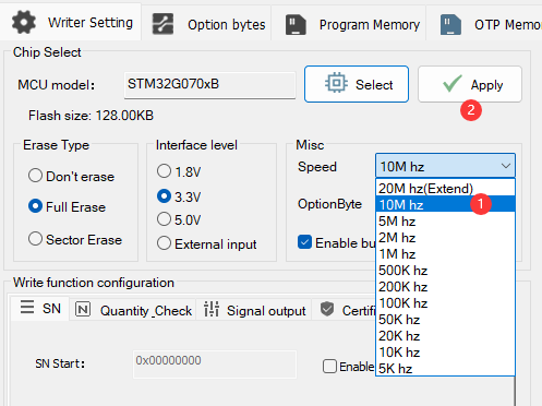
6:Try to adjust the clock speed
In different environments, the clock speed of the PowerWriter® programmer mode is higher than that of the Debugger mode. For example, in the MDK system environment, the default clock speed is 1Mhz, and the default clock speed of the PowerWriter® is 10Mhz, so there may be a situation in which the MDK is able to connect to the target chip but the PowerWriter® fails to do so. There may be cases where the MDK can connect to the target chip, but the PowerWriter® connection fails. You can try to reduce the clock speed to, for example, 5Mhz, etc. In some applications, the MCU firmware has enabled read protection, so you need to connect to the target chip with a faster speed, and you need to adjust the clock speed to a higher speed, or else you may have a handshake failure (the system enters into the protection state, and the debugging port is turned off). settings to the PowerWriter® device, as shown below: