3.1.10:Fast Offlining
This document demonstrates the configuration process for rapid offline production after receiving the PowerWriter® from 0. The reference chip is the N32G032P6W7 from Nations, and the process is the same for other chips, so we will describe how the whole process works.
1:Prepare
Before configuring the PowerWriter® offline production project, you need to prepare the PowerWriter® client software, the firmware data to be programmed, and know the pins and configuration methods of the signal interface of the PowerWriter® programmer, as well as some of the special functions of the process.
1.1 Installing the PowerWriter® Software
PowerWriter® software can be obtained through the following site, and then install the client software, the software is completed to start the software, PowerWriter® supports Win7 or above system.

Note: If there is no network in your environment, you can contact our customer service to get the installation package, the installation package in both places are the same installation package.
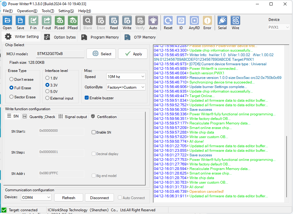
After downloading the installation package, unzip the zip package, run PowerWriter_x.x.x.x.x_installer.exe to install the PowerWriter® client software, start the software after the installation is complete, and enter the PowerWriter® main interface, as shown in the following figure:
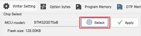
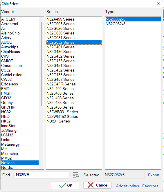
1.2 Select Target Chip
Take N32G032P6W7 as an example, select N32G032 in the Select Chip button.
1.3 Confirmation of target chip connection
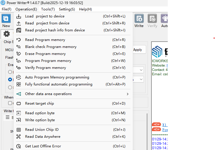
On the far right side of the PowerWriter® software toolbar there is a way to view the Chip Connection Diagram, as shown below:
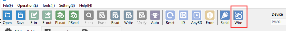
Or look through the menu:
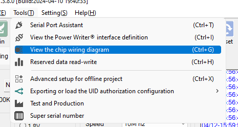
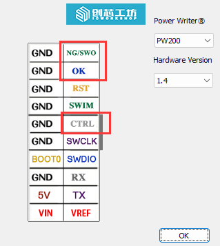
You can see the signal wiring diagram of PowerWriter® as shown below, you only need to connect VEXT, GND, DIO, CLK, NRST and BOOT0 are auxiliary signals, such as programming normal, can not be connected.You can click the buttons below to switch between different chip packages.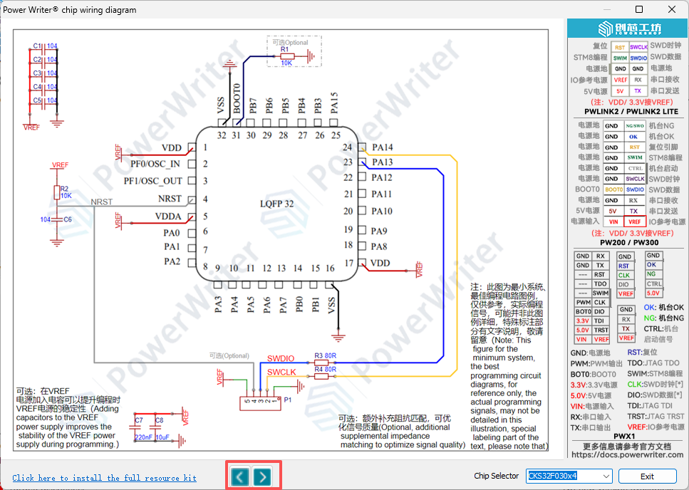
The interface signals of the PowerWriter® are shown as the socket pin in the above figure, and can also be viewed via the Menu -> Tools -> View PowerWriter® Interface Definition button.


Referring to the information as above, connect the target board and chip to confirm the connection method, at the same time the PowerWriter® software indicates that the target chip is connected, as shown below:
04/12-17:06:39:645> Update programmer Settings complete...
04/12-17:06:39:676> Update chip information successfully...
04/12-17:06:41:933> Target Online...
2:Basic parameters
2.1 Erase Method
You can choose between full-chip erase or page erase based on actual application requirements. If there are no special requirements, the default setting is recommended.
- Full-chip erase (default): This erases all data in the chip before writing. If the firmware size exceeds half of the chip's capacity, full-chip erase ensures better efficiency.
- Page erase: If the firmware is small or certain data needs to be preserved, you may choose page erase, which only erases the sectors that require updating.
The erase method setting applies to both online full-automatic programming and offline button-based programming. However, the Erase button located at the top of the software interface defaults to full-chip erase and is not controlled by the erase method setting described above.
2.2 interface VREF
The default interface level is 3.3V, which matches the IO voltage of the target chip, just match it according to the IO level of the actual chip.
2.3 Programming speed
Default is 10Mhz, if the working environment has less interference and the external wiring is shorter (less interference), then it can be changed to 20Mhz, if there is a failure during the programming process, then you need to change it back to 10Mhz, or reduce the speed.
Note: Unless the chip itself is defective, a chip that fails to programming in can be re-programmed and will not lead to chip scrapping.
2.4 Option byte update method
There are four modes in total. The default mode is "Restore Default → User Settings". You may adjust this according to your actual needs, or leave it unchanged.
No Operation → No Operation:
No action is taken on the option bytes before programming, and no action is taken after programming.
No Operation → User Settings:
No action is taken on the option bytes before programming; after programming, the user-defined option byte settings are written.
Restore Default → No Operation:
Option bytes are restored to their factory defaults before programming; no action is taken on the option bytes after programming.
Restore Default → User Settings:
Option bytes are restored to their factory defaults before programming; after programming, the user-defined option byte
settings are written.
2.5Offline Programming Mode
Blank check: Before programming, the programmer checks whether the chip is blank. If the chip is not blank, the programmer will report an error immediately and skip programming. If it is blank, programming proceeds normally.
Verify-only mode: During programming, the programmer compares the firmware to be programmed with the data already on the chip. No actual writing occurs; the programmer only returns a result indicating either "Verification Successful" or "Verification Failed."
3:Offline programming Behavior Settings
3.1 Auto start/stop programming
Turn on the automatic chip detection function, you can start the programming without pressing the key during the offline programming (you need to start it for the first time), and it will start the offline programming automatically when connecting to the target chip, as shown in the following figure:

3.2 Limit the count of offline programming
If you need to limit the number of offline programming times, please enable the function of limiting the number of programming times and limit the number of times as shown below:

4:Option Byte Configuration
If you need to programming special option words after programming the firmware, such as read protection to prevent the chip from being read out, set RDP1 and RDP2, and set RDP1 to RDP2, and set RDP2 to RDP2.
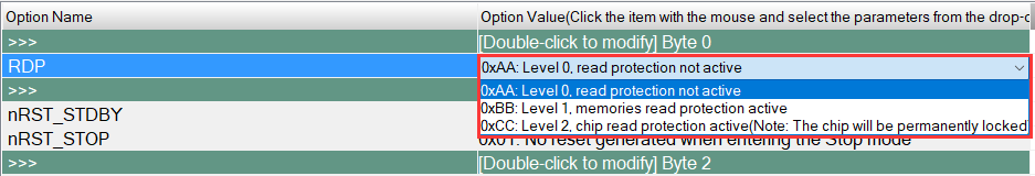
As above set to level 1 protection, if you need to completely disable debugger access after programming, you can set RDP2 to L2 as shown below:

If L2 is set, the target chip cannot be connected to the debugger (programmer) after programming is completed.
5:Importing firmware data
After the basic setup is completed, you can import the project's firmware data into the PowerWriter®, through the Add Firmware button in the Program Memory page, import the firmware in intel Hex, Raw binary , srec record (s19) format file, after importing, a confirmation box will pop up as shown below, after confirming that there is no error, click on the OK.

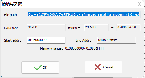
GCC compiler compiled firmware may pop up firmware selection box (prompting the loaded file has more than one firmware), which is related to the compiler's firmware output form, arm complier output file default padding 0xff, GCC is segmented output valid data segments, if there is more than one segment of the firmware, generally choose to merge the add can be added, if the add fails to prompt beyond the space, generally in the compilation of the project, set the address beyond the Flash space, such as compiling memory code, but did not deal with, or in the project, the option byte is also compiled into, there will be such a prompt, such as not sure how to deal with, please contact us for technical support.
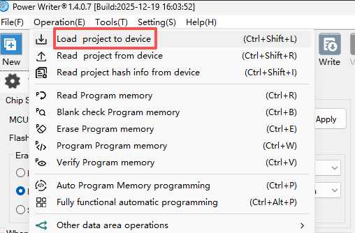
6:Importing a project to programmer
After everything is ready, you need to import the project into PowerWriter®, you can do it through the menu Execute Offline Load, or the toolbar shortcut buttons, Note: When loading the project offline, if the current data has not been saved as a project file, you will see the message of whether or not you need to save it.

When you save the project, set the save path of the project to avoid the loss of the configured programming data, and you can also set a password for the project for data protection to avoid data theft by others.

After the project is configured, it can be reused subsequently without having to reconfigure it each time, just load it into the programmer to deliver it to the production line, and if you need to update the data, recycle it back from the production line and reload the new data into the programmer.
After loading the project into the programmer, you must first disconnect from the software before pressing the button to start programming, as shown in the figure below:


6.1 Operational Demonstration
7:Delivery programmer to the production line
After the programmer is configured with data, the programmer can be delivered to the production line for production.
8:Confirmation of programming results
programming results, given in three ways:
Two beeps from the buzzer means success. More than two sounds means failure. If the comparison production line requires no ringing (noisy), the buzzer can be turned off when configuring the basic parameters.
Green light indicates success, red light indicates failure.
Interface signals: OK output is high to indicate successful programming, NG output is high to indicate programming failure, you can use the signals from these two pins to access the automation control system.
9:Common problems
9.1:Auto-detect is on, but it doesn't respond when you put the chip in.
The PowerWriter® requires a manual button press to start the automated process for the first time to ensure that the production environment is ready and to avoid incorrect programming when the production line is not ready.
9.2:Auto-programming function is automatically turned off when programming fails
If you use the programming test rack, press the way, the failure of the case is very low, only in the manual use of tweezers to pick up the bare core due to the lack of alignment or poor contact may lead to failure, this case can be adjusted to increase the de-jittering time of the automatic detection.
After the automatic programming function is turned off, it is usually necessary to manually verify the production environment, and after the verification is complete, press the button again to resume the automatic detection of the chip programming process.
9.3:Failure error when problematic backtracking
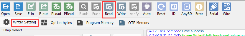
PowerWriter® products for sale do not have a screen, but they do record the last error code, which can be read by the PowerWriter® software to obtain the type and description of the error.

For occasional programming failures, try to lift the programming test rack and press it again. If the same board (chip) fails more than 2 times, it will be sorted out, if necessary, please contact us.
9.4:programming state back and data back
Projects that have been loaded into PowerWriter® can be read internally by going to Menu -> Perform Offline Read and Save, (if a password has been previously set, a password is required to view the data).

Or backtrack the current programming status, such as the number of programmings remaining, by doing the following
9.5:programmer Marker
The programmer can be marked by menu Tools -> Reserved Data Read/Write, as shown below:

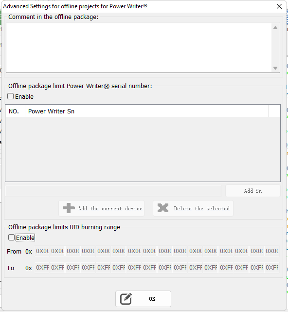
9.6:Tagging PowerWriter® Projects
You can make a note of the project in the menu Tools -> Advanced Settings for Offline Production Projects -> Offline Files, as shown below:
10:Contact & Feedback
If you encounter any problems, suggestions or comments in the process of use, promptly contact us.