3.4.9.1: 4-Ch Programming
The procedures described in this document apply only to the Renesas custom 1-to-4 device. The programmer model is PWX1. It is not compatible with standard devices sold on the open market: there are subtle hardware differences, custom accessories are required, and the device is intended for use in specific scenarios only. Upgrading a standard PWX1 device to the custom firmware is prohibited (custom resources are marked with a dedicated "custom-only" label on the download page). If a standard device has been accidentally upgraded with the custom firmware, please downgrade it back to the general firmware using the standard edition of PowerWriter®, and contact customer service and technical support if necessary.
1.Introduction
This document is a quick start guide for the Renesas custom 1-to-4 project developed by the PowerWriter® team. The device is sold and used in specific scenarios only. If you have not purchased this custom 1-to-4 device, please close this page and stop reading.
This document is intended to provide a quick entry point for using the Renesas 1-to-4 device. It covers, but is not limited to: download links for software and firmware releases (so that users can obtain the latest resources and support information from the download site in time), device wiring, basic usage of online functions, basics of offline programming, usage with automated programming machines, cloud platform tutorials, as well as limitations of online and machine programming, and solutions to common problems.
Although this is a custom device, the PowerWriter® team has made every effort to keep software compatibility. Except for the notes specifically mentioned in this document, most of the PowerWriter® features described on this documentation site work normally.
2.Software Download
All bundled resources can be downloaded from this link: ICWorkshop • PowerWriter, as shown below:
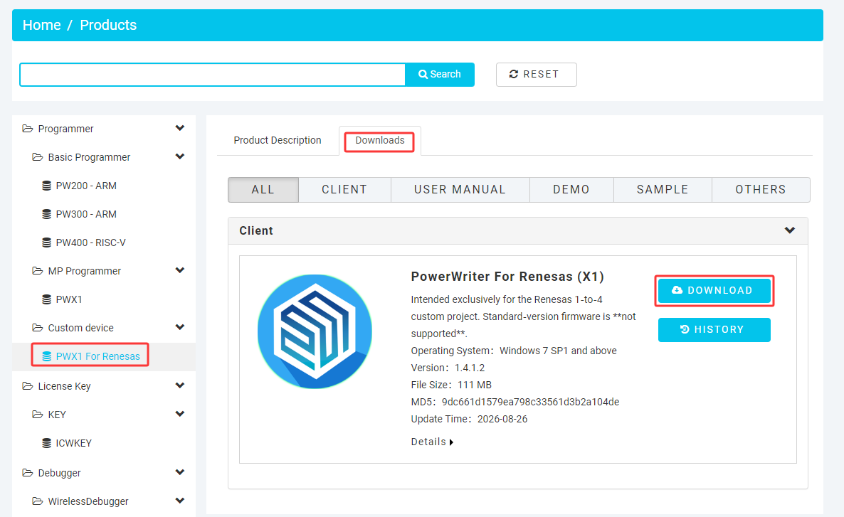
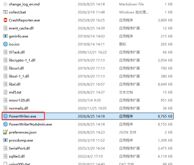
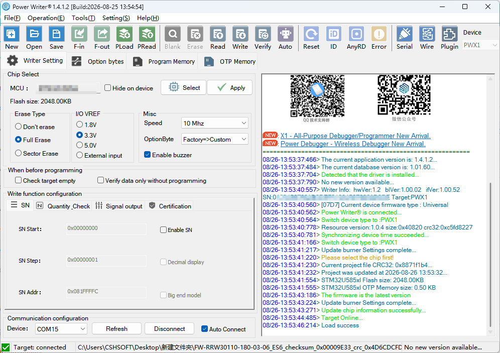
After downloading, extract the archive and double-click PowerWriter.exe or PowerWriterNoAdmin.exe in the extracted folder to run the software, as shown below:
2.1: Software Upgrade
The bundled PC-side software does not currently support online upgrade. New releases are published via the download link above. Please keep an eye on the changelog and release date of the latest version. If you are unsure of your current version, simply download from the download site, extract, and run.
2.2: Firmware Upgrade
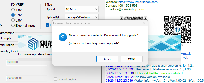
New firmware is released together with the new client software. After the software starts and connects to the programmer, it automatically checks for firmware updates; if a new firmware version is detected, you will be prompted to update the firmware, as shown below:
3.Preparation
3.1: Package Contents
The device comes with the following accessories:
- 1× white USB Type-C cable (for communication between the PC and the programmer)
- 4× black USB Type-C cables (for communication between the device and the MCU (device terminal))
- 1× DC 12 V / 3 A power adapter
- 1× dedicated signal adapter board for the 1-to-4 setup
- 1× custom PWX1 programmer
3.2: Wiring
Connect the PC to the PWX1 programmer and the programmer to the target chips as shown below:
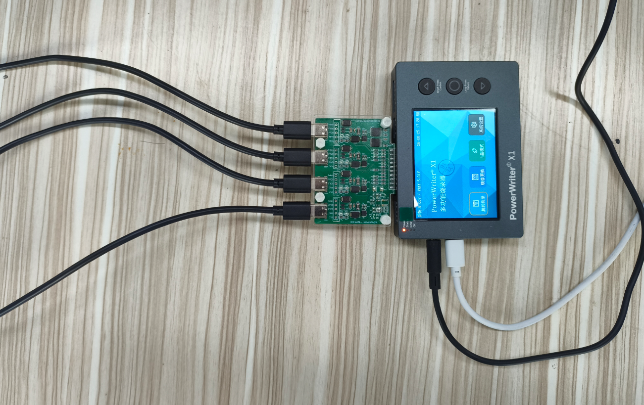
The DC power adapter must be connected; otherwise, insufficient power will cause programming to fail.
3.3: Device Communication
When online programming is needed or a project needs to be loaded into the device, the PC must be connected to the programmer. The programmer connects to the PC via the white USB Type-C cable. As described in the previous section, once the PowerWriter® software is connected to the programmer, device information is displayed in the log panel, as follows:
08/26-10:33:48:854> Writer Info: hwVer:1.2 blVer:1.00.02 ifVer:1.00.52 SN:0**************************E Target:PWX1
3.4: Chip Initialization
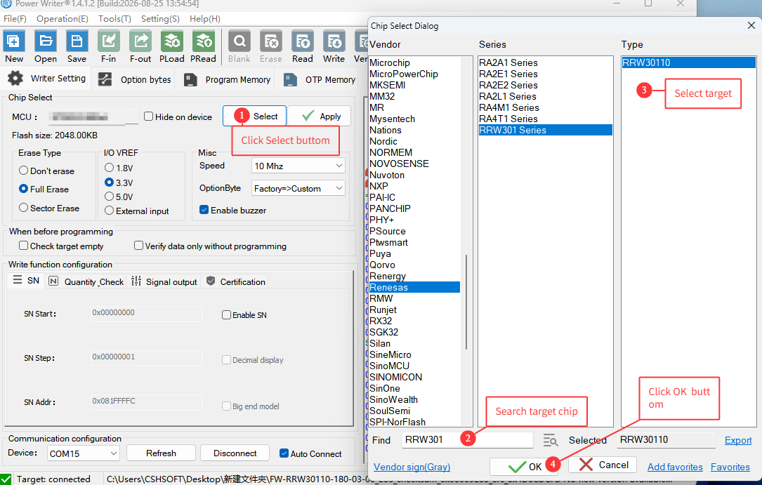
On the programmer settings page, click the Select Chip button, then search for the specific Renesas chip model to be programmed. Taking RRW30110 as an example, the procedure is as shown in the annotated figure below:
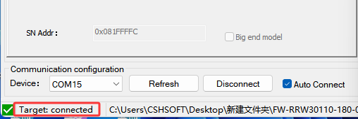
Once communication between the target chip, the programmer, and the PC client software is successfully established, a target-chip-connected indicator appears in the lower-left corner of the PC software, as shown below:
3.5: Signal Indication
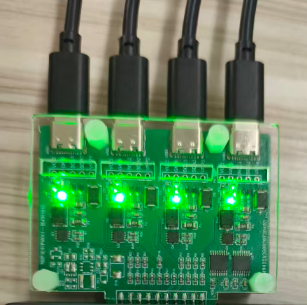
- The signal adapter board shows the operation result of each of the 4 channels independently: green for success and red for failure.
- The status indicator on the programmer itself works as follows: it shows green (OK) as long as at least one channel succeeds, and shows red (NG) only when all channels fail. It is recommended to use the per-channel status LEDs as the reference.
- The machine signal port behaves consistently with the programmer status: the OK signal is asserted (active high) when at least one channel succeeds, and the NG signal is asserted (high) only when all channels fail. For details, refer to 2.1 Functional Parameters | PowerWriter Documentation Center.
- Client software logs and status: consistent with the programmer LEDs and the machine status — success is reported as long as one channel succeeds, and failure is shown only when all channels fail.
Since automated programming machines do not have 4 independent channel statuses, it is recommended that each machine connects to only one channel, so that the machine can sort the target chips.
4.Operations
4.1: Adding Firmware Files
The PowerWriter® client supports the Renesas proprietary in firmware format, including full firmware mode and differential firmware mode, with automatic detection. The procedure is as follows:
Step 1:
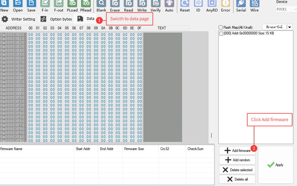
Step 2:
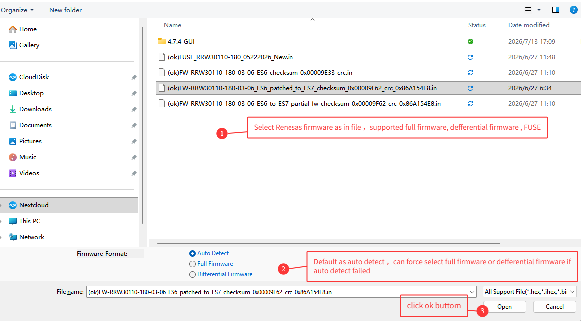
Configuration words can also be added via files. You can add multiple files to be written to the target chip (device) at once, such as configuration words and firmware files.
4.2: Online Programming
After connecting the target chips via the black Type-C cables, click the Auto button on the toolbar, as shown below. 4-channel online programming then starts automatically, and the programming status of the four channels is displayed when finished, as shown below:

4.3: Offline Programming
After adding the files to be programmed, click the Load button on the toolbar to load the data into the device, enabling offline programming. The procedure is as follows:
Step 1: Load the data by clicking the Load button

If the project file has not been saved to disk, you will be prompted to save it on the first load. It is recommended to save the project file to disk so that it can be reopened and used directly later.
Step 2: Disconnect the PC software from the device and make sure the button state is as shown

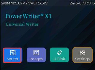
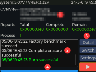
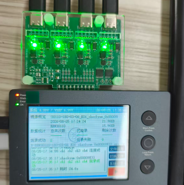
Step 3: On the device, switch to the offline programming menu and click the Start/Confirm button to start offline programming, as shown below:
5.More Information
- For the complete product manual and tutorials, refer to: Release Information | PowerWriter Documentation Center
- Cloud platform tutorial: ICWorkshop Quick Guide | PowerWriter Documentation Center
6.Feedback and Technical Support
If you have any questions, please send feedback to: cs@icworkshop.com. For more feedback channels, refer to the product manual or check Release Information | PowerWriter Documentation Center.