5.1 Flash-IC Socket
In addition to providing the standard burn-in socket, it is also possible to use PowerWriter Flash Socket bom Download and burn the reference design from the page. Adjust the machine according to your own needs. If you have any customized requirements, please contact and feedback to cs@icworkshop.com.
PowerWriter X1 device, support SPI Nor Flash/SPI NAND/I2C EEPROM/Microwire EEPROM Flash chip, because the FLASH burner is relatively unified, at the same time good versatility, In order to improve the stability of programming, PWX1 device can choose a standard Flash burner, the current summary of the burner list reference is as follows:
- DIP8
- SOP8-150:
- SOP8-150 : (lead pitch: 1.27mm) / (package width: 3.8mm/150mil)
- SOIC8-150 : (lead pitch: 1.27mm) / (package width: 3.8mm/150mil)
- SOP8-200
- SOP8-200 : (lead pitch:: 1.27mm) / (package width: 5.2mm/200mil)
- SOIC8-200 : (lead pitch:: 1.27mm) / (package width: 5.2mm/208mil)
- SOP8-208 : (lead pitch:: 1.27mm) / (package width: 5.2mm/208mil)
- SOIC8-208 : (lead pitch:: 1.27mm) / (package width: 5.2mm/200mil)
- TSSOP8-170
- TSSOP8-170 : (lead pitch: 0.65mm) / (package width: 4.4mm)
- MSOP8
- MSOP8 : (lead pitch: 0.65mm) / (package width: 3mm)
- UDFN8-3×2
- USON8 : (lead pitch: 0.5mm) / (width x height (exclusive pad): 3x2mm)
- UDFN8 : (lead pitch: 0.5mm) / (width x height (exclusive pad): 3x2mm)
- DFN8 : (lead pitch: 0.5mm) / (width x height (exclusive pad): 3x2mm)
- QFN8 : (lead pitch: 0.5mm) / (width x height (exclusive pad): 3x2mm)
- SOT23-6
- SOT23-5 : (lead pitch: 0.95mm)
- SOT23-6 : (lead pitch: 0.95mm)
- WSON8-8×6
- WSON8 : (lead pitch: 1.27mm) / (width x height (exclusive pad): 8x6mm)
- QFN8 : (lead pitch: 1.27mm) / (width x height (exclusive pad): 8x6mm)
- WSON8-6×5
- WSON8 : (lead pitch: 1.27mm) / (width x height (exclusive pad): 6x5mm)
- QFN8 : (lead pitch: 1.27mm) / (width x height (exclusive pad): 6x5mm)
- USON8 : (lead pitch: 1.27mm) / (width x height (exclusive pad): 6x5mm)
- others
5.1.1 Suggest
Flash burner is customized for PWX1. When selecting the burner, you only need to select the burner according to the Package of the chip. For example, the Package type of a Flash chip is marked in the manual package type below. The names are called SOIC 208-mil and WSON. When the Flash packaged with SOIC is selected, the burning seat of SOP8-200 can be used for burning. When the chip is WSON 6x5, the burning seat can be used: WSON8-6×5A, and so on.

5.1.2 Usage
5.1.2.1:Socket configuration
PWX1 flash burner, will be combined with a variety of Flash package, compatible with a burner, because different chip pins may be different, so, on the burner, reserve a three-speed dip switch, as shown below, and on the burner for the direction of the switch marked, as shown below:

Take the package of WSON8-6X5 as an example, the default dip switch is all up, when using Microwire's EEPROM (with ORG pin ), the dip switch is all down, you can achieve all WSON8 package Flash chip programming .

5.1.2.1:Connect directly
Flash burner can be directly connected to the burner.
Only when burning Flash chip , can be inserted to avoid IO signal inconsistency, damage to the burner signal IO.
5.1.2.2:Use JTAG wire extension
Use standard 20-PIN JTAG cable to connect the device to the burner for extension.
5.1.3:Flash chip ISP adapter
5.1.3.1:Adapter board size
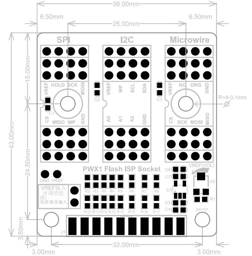
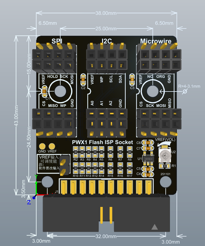
5.1.3.2:Usage
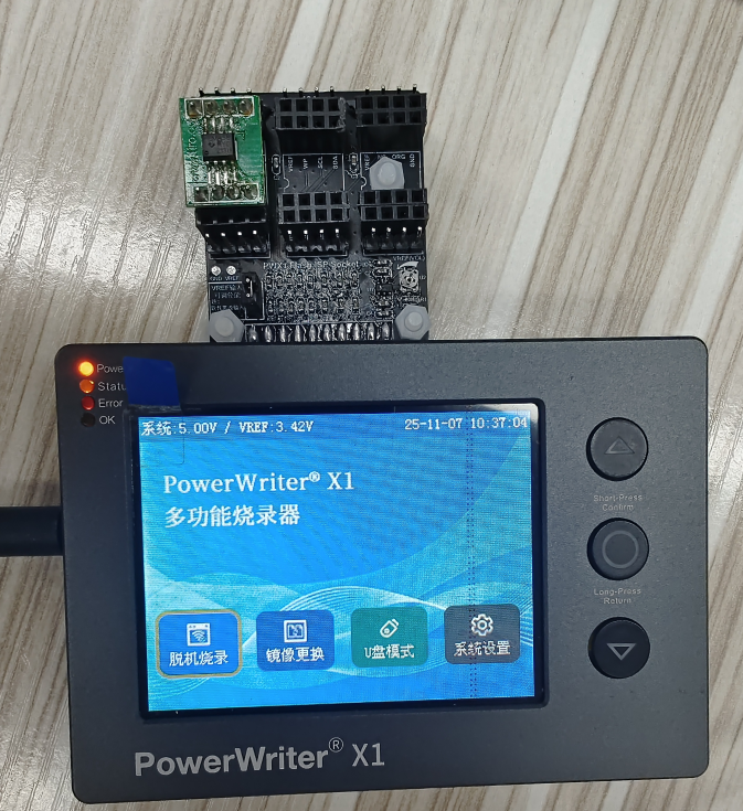
The connection method of PWX1 and the flash ISP programming socket is as follows:
The jumper cap is by default not connected. If you want the VREF to be connected only when the input is provided, please refer to the usage in Chapter 5.1.3.3.

Pay attention to the position of pin 1 on the burn-in socket. The location with the crescent-shaped marking represents pin 1.
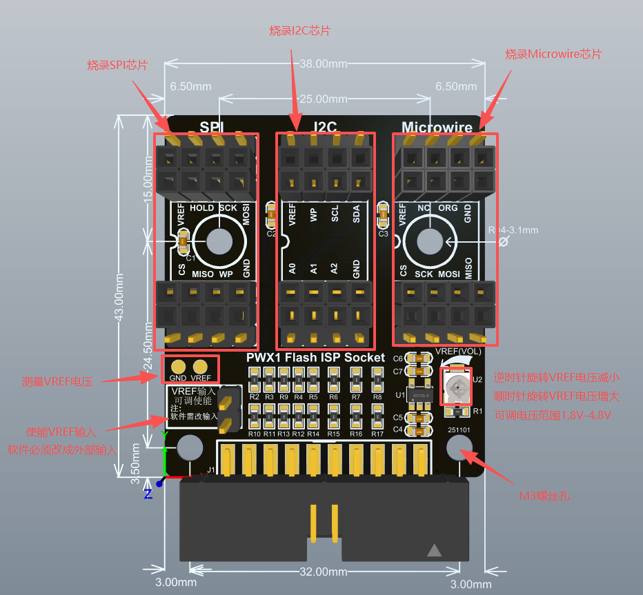
The pin-out interface is suitable for board-to-board programming. Simply insert the flash board into the pin-out area to perform the programming, as shown in the following picture:
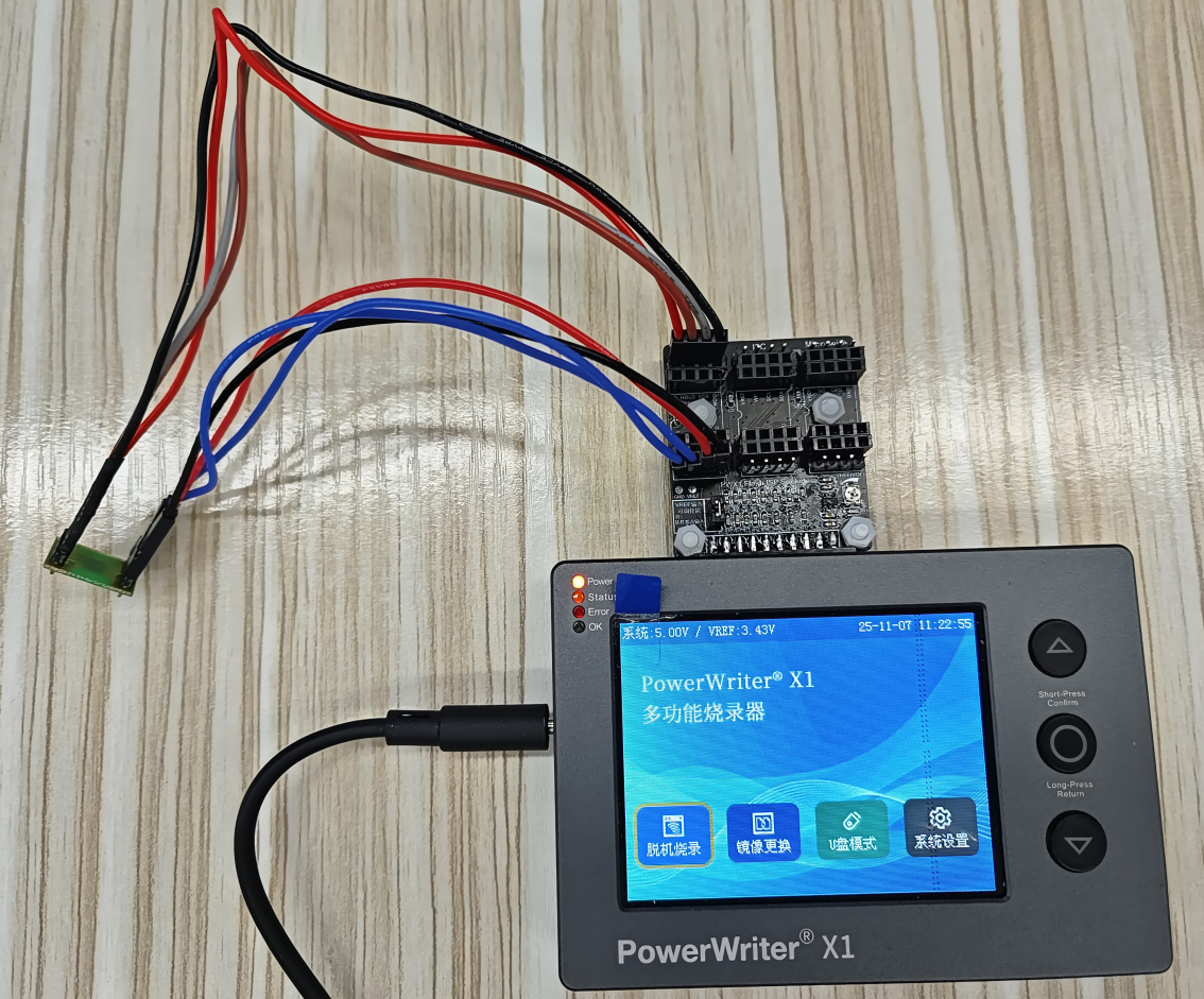
The pin connector interface is suitable for wire-bonding and burning the target chip through DuPont wires. As shown in the following figure:
5.1.3.3:Fine-tune the voltage
Method 1: First, on the upper computer of PowerWriter, change VREF to external input, and select "Follow Image" for the device:

Method 2: Through the system settings, set the VREF voltage to be fixed as the external input reference, as shown in the following figure:
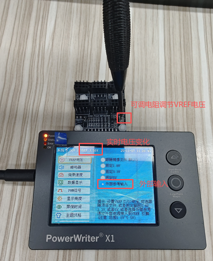
Then, the jumper is short-circuited. By rotating the adjustable resistor with a screwdriver, the continuous adjustment of the VREF programming voltage can be achieved. The adjustable range is from 1.3V to 4.8V. During the rotation process, the VREF voltage will be displayed on the interface in real time.
5.1.4 Query
Visit https://www.powerwriter.com/index/index/chip_search.html Query the burner information according to the chip.