2.1: Features and Parameters
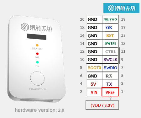
PW200/PW300 hardware version 2.0 and above are upgraded with OLED status display; other features remain unchanged.
The interface definition parameters described in this section apply to PW200, PW300 devices, and the functional parameters apply to all PowerWriter® devices.
- For PWX1 devices, please refer to PWX1 Features and Parameters.
- For PWLINK2 (Lite) devices, please refer to PWLINK2 Features and Parameters.
- For PW400 devices, please refer to PW400 Features and Parameters.
- For ICWKEY devices, please refer to ICWKEY Features and Parameters.
For status descriptions of different products, please refer to PowerWriter® Device Operating Status Description.
2.1.1 Introduction
PW200/PW300 is an integrated comprehensive development tool officially launched by ICWorkshop, combining a universal debugger, online programmer, and offline programmer in one device. It is primarily aimed at individual developers, small-batch production, and authorization control. With rich features and secure design, it meets developers' needs throughout the entire process from development and debugging, online verification, to product mass production.
Different product models have slight differences in features. The full-featured device is PWX1 (abbreviated as X1). For details, see PWX1 User Manual.
2.1.2 Product Parameters
- Product Dimensions: 92.000mm 56.000mm 16.000mm
- Operating Voltage: DC 5V
- Power Consumption: 30mA@5V~100mA@5V
- Drive Capability: 5V@700mA (Max)
2.1.3 Package Contents
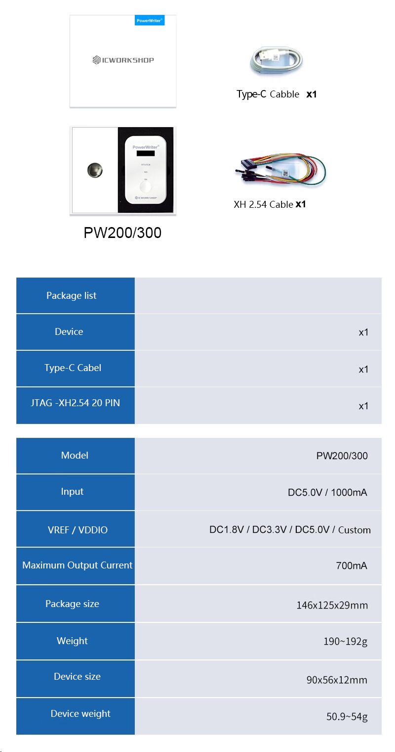
2.1.4 Interface Signals
2.1.4.1 Output Port
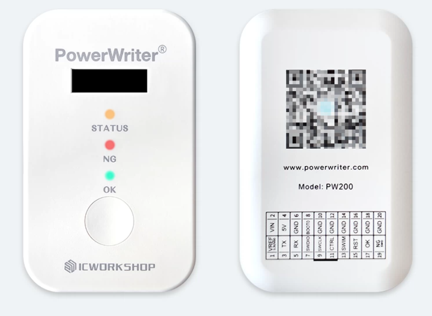
The PW200 (PW300) interface combines programming machine signals, TRACE signals, SWIM signals, standard serial port signals, BOOT0 control, and power supply (power supports output of 1.8V, 3.3V, 5.0V, and can also serve as an input reference to provide logic level for PowerWriter®), as shown in the figure below:
| Name | Description |
|---|---|
| VREF | Target chip IO reference voltage output (VDDIO) |
| VIN | Device alternative power supply (supports voltage range 5.0V~5.5V) |
| 5V | Default 5V voltage output (commonly used for driving the mainboard, configurable to 3.3V) |
| GND | Power ground |
| TX | General serial port, ISP programming, unlock transmit (device side) |
| RX | General serial port, ISP programming, unlock receive (device side) |
| SWDIO | SWD interface data line SWDIO |
| SWCLK | SWD interface clock line SWCLK |
| BOOT0 | Target chip BOOT control pin |
| SWIM | SWIM interface data line |
| RST | Target chip auxiliary reset control pin |
| CTRL | Programming control (low pulse start) |
| OK | Programming success status output (output high) |
The VREF (VEXT) voltage is the target chip IO reference voltage. It can be set via the configuration software to output 1.8V, 3.3V, or 5V, or configured as an external input reference voltage to switch the PowerWriter® logic level based on the external chip's operating voltage.
Different hardware versions and models may have slight differences in interfaces. Please refer to the actual device. New versions are compatible with older designs and provide more features.
Power Writer supports power supply from the USB interface and from the programming port VIN to power the device:
| Power Supply Method | Input Voltage | Description |
|---|---|---|
| USB | DC 5V | Ensure sufficient input drive capability |
| VIN | DC 5V | May not work below or above this range |
2.1.4.2 Main Panel
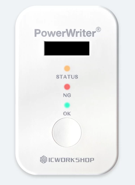
2.1.4.2.1 LED Indicators
- POWER: Power indicator (blue).
- STATUS: Status indicator (yellow).
- NG: Programming failure indicator (red).
- OK: Programming success indicator (green).
- Screen: Real-time display of device operating status. For details, refer to OLED Status Display.
2.1.4.3 Main Button
When the button is pressed briefly, offline programming starts.
During offline programming, please close the PowerWriter® application or disconnect the device before operating.
2.1.4.4 Status Description
| Signal Name | Signal Description |
|---|---|
| POWER LED | Always on when powered on |
| STATUS LED | Off when powered on with no operation |
| Flashes during communication with the application software, flash rate follows the communication speed setting | |
| Flashes during offline programming, flash rate follows the communication speed setting | |
| Stays on when connected to the target chip | |
| NG LED | Lights up when an operation error occurs, such as read, erase, or programming failure, and turns off when a new operation starts |
| OK LED | Lights up when read, erase, or programming operations succeed, and turns off when a new operation starts |
| Buzzer Frequency | PWM frequency is 2.7K Hz (defined as follows) |
| Buzzer Count | Beeps once when powered on with no operation |
| Beeps once when connected to the target chip | |
| Beeps twice when programming succeeds or offline project download succeeds | |
| Beeps three times when an operation fails | |
| Beeps four times when offline programming count is 0 | |
| Button | Effective for offline programming (released trigger, press longer than 1s ignored) |
| OK Signal Pin | Outputs high when offline operation succeeds, cleared when a new operation starts |
| NG Signal Pin | Outputs high when offline operation fails, cleared when a new operation starts |
| CTRL Signal Pin | Input >=40ms low signal to start one offline programming session |
2.1.4.5 OLED Status Display
Tip: Only devices with hardware version 2.0 and above support this feature. Please check the device information bar:
05/12-16:47:00:973> Writer Info: hwVer:2.0 blVer:x.xx.xx ....
The PW200/PW300 provides bilingual Chinese-English OLED display with a resolution of 128x32 and font size of 12 pt. The factory default is English display. When connected to the PowerWriter client software, the device automatically synchronizes with the client language settings.
2.1.4.5.1 Startup Screen

2.1.4.5.2 Display Overview
Display Mode 1 (mainly in offline mode):

The screen content display is divided into four areas:
- Project file or working mode display: Used to display current project file information and working mode information.
- Information display: Displays dynamic information within the project file, such as checksum information.
- Status: Displays the current operating status of the device.
- Progress display: Displays the current operation progress, mainly shown during offline programming.
Display Mode 2 (mainly in online mode):

The screen content display is divided into three areas:
- Working mode: Used to indicate the current working mode of the device
- Status information: Displays the current working status.
- Progress display: Displays the current operation progress, such as showing progress when programming data.
2.1.4.5.3 Idle State
2.1.4.5.3.1 Without Project File

2.1.4.5.3.2 Device with Project File Loaded

- Project file name carousel.
- Project file basic information carousel, including firmware checksum, serial number, and other basic information.
- Current device status.
With firmware upgrades, the carousel display information may be adjusted. This document will not provide additional notices. Please pay attention to the carousel information display.
2.1.4.5.3 Online Mode
When the device is connected to the PowerWriter client software, the device will display the working mode and status changes in real time. In online mode, the display mode is always Display Mode 2. Please refer to Display Overview. Online mode mainly includes the following modes:
- USB mode (connected to the client)
- Bluetooth mode (connected to the PowerWriter WeChat Mini Program)
- AT mode (communicating with the device using the PowerWriter AT Core open-source library)
- Debug mode (when IDEs such as Keil/GDB/IAR are connected to the device)
- UART CDC forwarding (when the device is in CDC forwarding state)
- Other modes
In online mode, all working status processing follows the same information flow. This section uses USB mode as an example to illustrate the display content under different states.
2.1.4.5.3.1 Communication Established

After communication is established, the current working mode and status will be displayed.
2.1.4.5.3.2 Progress Display

Some online commands also display progress information. For example, loading data will show a progress bar at the bottom, as shown in the figure above.
2.1.4.5.3.3 Error Occurrence

During communication, if an error occurs, the error description will be displayed in real time.
2.1.4.5.3.4 Communication Disconnected

When disconnected, it displays that the device has been disconnected, as shown in the figure above.
2.1.4.5.3 Offline Mode
2.1.4.5.3.1 Standard Mode
In offline programming mode, the OLED will display current project information, working status, progress, BUSY, success or failure status, as shown in the figure below:

- Current project file scroll display.
- Project file basic information display.
- Busy/Success/Failure status display (BUSY/OK/NG).
- Progress display.
2.1.4.5.3.2 When an Error Occurs

When an error occurs during offline programming, the detailed error reason will be displayed. Based on this information, you can troubleshoot the error, as shown in the figure above.
2.1.4.5 Features
Supports data encryption.
Supports project import/export.
Supports loading encrypted projects to PowerWriter® for offline production control.
Supports reading offline projects from PowerWriter®. (Note: correct password required).
Supports online chip Program Flash area reading.
Supports online chip Program Flash area read address and read size settings, full chip reading function, making it easy to read target chip firmware data.
Supports online chip blank check.
Supports online chip erase. Developers and users can directly erase the target chip through the software.
Supports online programming of Program Flash area data. Users can write firmware via online programming without having to use offline mode or debuggers like MDK/IAR/CUBEIDE.
Supports online verification of Program Flash data.
Supports online automatic programming, automatically executing erase, write, verify, and update Option Byte functions.
Supports online target chip reset.
Supports setting read protection: Level-0, Level-1, Level-2 levels can be set, and automatically identifies whether the user's protection bits are enabled.
Supports complete Option Byte settings list.
Supports complete Option Byte default settings.
Option Byte supports multiple languages.
Supports automatic recognition of Option Byte options and execution of corresponding operations.
Supports online factory Option Byte restore
Supports online Option Byte reading
Supports reading option bytes of locked chips
Supports online Option Byte writing
Supports saving user-defined option bytes. Users can save configured option bytes to a file and send it to the programming factory or use it for other purposes
Supports loading user-defined option bytes from saved files into the project
Option Byte dynamic real-time synchronization, automatically syncs to PC client when connected to target chip
Supports Bank automatic recognition
Supports multiple Option Byte update methods
No operation before programming -> No operation after programming
No operation before programming -> Write user-defined Option Byte after programming
Restore factory Option Byte before programming -> No operation after programming
Restore factory Option Byte before programming -> Write user-defined Option Byte after programming
Supports online reading of target chip Chip ID, making it easy for users to check Chip ID. Non-contiguous Chip IDs are automatically presented in continuous address format.
Supports online reading of target chip internal data at any address, mainly for developer debug analysis of target chips, with configurable read address and read size. See relevant chapters for details. Mainly used for:
Reading any memory data
Reading any Flash data
Reading any register data, etc.
Supports automatic online software upgrade (when network is available)
Supports multiple languages, fully supports mainstream ARM Cortex-M chips
Supports multiple erase methods: Page erase, full chip erase, Bank automatic recognition erase (no user selection required)
Supports multiple voltage selections: 1.8V/3.3V/5.0V or user-defined reference voltage
Supports free adjustment of programming speed, 5KHz~10MHz speed freely adjustable
Supports online buzzer notification tones. For definition rules, refer to the signal definition description chapter
Supports serial number writing, with configurable serial number address, initial value, step size, and endian mode
Supports serial number decimal and hexadecimal display switching
Supports serial number address legality check (automatically checks for overlap with other setting addresses)
Supports offline programming count setting, up to 4.2 billion times
Supports automatic chip detection, auto start/stop programming when chip is inserted
Supports setting auto chip detection stabilization time, default 100ms
Supports setting chip removal delay time during auto programming, default 100ms
Supports decimal and hexadecimal display switching for programming count settings
Supports legality check of programming count setting parameters
Supports starting target chip after programming (Reset & Run)
Supports turning off power output after target chip programming. In batch programming, turning off power after programming effectively protects chips from being removed from the programming socket while powered.
Supports setting power stabilization time or power-down stabilization time before and after programming (valid when power output on/off option is enabled)
Supports RESET pin signal control, with the following three modes
Output constant low level
Turn off output (high impedance state)
Output reset then turn off (generate reset signal before programming)
Supports data verification: verifies whether data programmed to the target chip is correct, enabled by default
Supports UID-based online chip authorization programming via ICWorkshop official authorization server
Supports Power Writer built-in offline authorization algorithm for chip authorization
Supports flexible configuration of Power Writer built-in offline authorization algorithm key storage address, key size (4/8/12 byte), key endian mode, and user-defined password function
Supports user-defined offline authorization algorithm function, beyond the existing modes
Supports automatic generation of random offline authorization algorithms. Power Writer can automatically generate random offline authorization algorithms, each unique with near-zero probability of duplication. Supports algorithm strength check and provides manual adjustment reference suggestions. Users can manually adjust or regenerate until satisfied.
Supports exporting Sample Project for custom offline authorization algorithms. Users simply need to compile the exported source code into their project to implement the offline authorization algorithm, convenient and fast. Through a comprehensive system kernel scheduling mechanism, Power Writer can execute concurrent operations
Supports complete online operation log display, providing timely user notifications. Logs mainly include the following colors
Light blue: Represents general operation results
Green: Represents successful operations
Red: Represents errors or other critical information, such as Power Writer disconnection
Yellow: Represents warnings, possible operation issues, or potential setting problems
Supports log reset, log saving. Want to save operation records? Try saving the log for backup, so you can clearly see the last operation flow when encountering problems in the future
Supports encrypted saving and loading of programming configuration parameters
Supports complete chip Flash space mapping, displayed in HEX view, allowing users to intuitively see the loaded raw data
Supports Flash data area copy and paste operations, allowing users to edit the Flash data area
Supports Flash data area address jumping, allowing users to quickly jump to specified addresses
Supports multi-segment firmware programming function with no limit on firmware quantity. Multi-segment firmware can display real-time firmware start address, end address, size, and CRC32 information
Supports custom firmware addresses. Users can customize addresses for binary format firmware and check address legality
Supports rich firmware formats: bin/Hex/S19/pkg formats (pkg format is ICWorkshop's custom format)
Supports adding random array function with no limit on the number of random arrays (under development)
Supports complete chip sector table viewing, allowing intuitive viewing of chip sector information: start address, end address, and size
Supports automatic identification of firmware corresponding sector information. When selecting firmware, the corresponding sectors can be seen
Supports online custom sector erase. Users can erase specified sectors online
Supports Bank automatic recognition. For single/dual Bank chips, when users sync modify or read Option Byte, the sector table follows the Option Byte settings for switching
Supports random filling of selected sector tables. Users can fill remaining free parts of Flash with random data
Supports starting offline programming via CTRL control signal
Supports manual programming: press the button to start programming
Supports LED status indication: LEDs indicate the operating status of the offline programmer. Four independent multi-color LEDs display POWER / BUSY / OK / NG status, rather than a single LED, making it more intuitive
Supports ICWorkshop server remote download
Supports ICWorkshop chip mass production authorization
Supports third-party self-built authorization server authorization
Supports machine signal output, providing NG and OK signals
Supports device current configuration reading (Note: some sensitive information will not be read and displayed)
Supports one-click firmware upgrade: simple and convenient, ensuring easy product upgrades. Software auto device detection: insert the device into USB and the software automatically detects the connection, no manual operation required
Supports programmer-to-target-chip data encryption, preventing user firmware data theft
Supports data encryption: device and PC communication data is encrypted multiple times to ensure data security
Device storage data encryption: firmware data stored in the device uses multiple encryption algorithms to ensure data cannot be decrypted
Supports automatic programming address validity detection to ensure program runs correctly
Multi-firmware simultaneous programming supports address overlap check
Compatible SWJ pin signals
Supports ARM core chip Debugger / Trace function. Power Writer is not just an online programmer and production programmer, but also a full-featured Debugger. It supports not only Cortex-M chip debugging but also Cortex-A CPU debugging
Mainstream USB HID communication method for debugging ARM core chips as a Debugger
Supports reading the last offline operation result for quick self-diagnosis of errors
Supports online simulation of offline programming. Through this function, all configured information can be written online, refer to smart automatic programming
Integrated serial port assistant
One-click export of the complete chip list currently supported by PowerWriter®
Supports multi-level speed adjustment. Standard edition supports up to 20MHz clock speed, professional edition speed reaches up to 50MHz
Supports option byte buffer direct editing, loading, and saving
Supports memory extension pages, such as: EEPROM, OTP, Flash loader, Data and other virtual block read/write
Supports adding random block function
Supports multi-firmware document format, segmented loading
Supports multi-firmware document format, merged loading
Supports real-time viewing of wiring reference for the currently selected chip
Supports CID reading
Supports programmer reserved data read/write
Supports adding notes to Pkg project files
Supports binding Pkg project files to programmer SN, with no limit on the number of bindings
Supports Pkg specified UID programming range
Supports target chip protocol layer encryption for programming.
Supports server remote online authorization. Production authorization can be controlled through ICWorkshop's built-in authorization server.
Supports third-party self-built server online authorization. By using the ICWorkshop authorization server development kit, third-party users can quickly build their own authorization server and customize authorization algorithms, independently controlling key product security authorization algorithms. ICWorkshop serves as the platform provider for production programming.
Supports built-in automatic Matrix offline authorization.
Supports ICWKEY asymmetric encryption algorithm hardware authorization algorithm. See the hardware authorization module user manual for details.
Supports custom ICWKEY secondary development. (requires official authorization)
Supports factory mode.
2.1.4.6 Supported Chips
- STM32 (STMicroelectronics) Full Series
- STM8 (STMicroelectronics) Full Series
- GD32 (GigaDevice) Full Series
- MM32 (MindMotion) Full Series
- HK32 (Hangshun) Full Series
- CS32 (Chipsea) Full Series
- Zbit32 (Zbit Semiconductor) Full Series
- HC32 (HuaDa Semiconductor) Full Series
- Artery (Artery Technology) Full Series
- Nations (Nations Technologies) Full Series
- SINOMICON (SINOMICON) Full Series
- Geehy (Geehy Semiconductor) Full Series
- Nuvoton (Nuvoton) Full Series
- WCH (WCH)
- Aisinochip (Aisinochip)
- Synwit (Synwit)
- innostar (Innostar)
- CMIOT (CMIoT)
- CKS (CKS)
- CW32 (Wuhan XinYuan)
- Cmsemicon (Cmsemicon)
- UNICMICRO (Unicmicro)
- Puya (Puya Semiconductor)
- PANCHIP (PANCHIP)
- PAI-IC (PAI-IC)
- LCM 8-bit + 32-bit (LCM)
- CubicLattice (CubicLattice)
- edgeless (Edgeless)
- Linko (Linko)
- Nordic (Nordic Semiconductor)
- FMD (Fremont Micro Devices)
- Qorvo (Qorvo)
- ChipNexus (ChipNexus)
- SinoMCU (SinoMCU)
- HED (HuaDa Electronic)
- Renesas (Renesas)
- RMW (RMW)
- A1SEMI (A1SEMI)
- Air (Air)
- AUCU
- GFCHIP (GFCHIP)
- MH (MH)
- TAE (TAE)
- XK32
- AisinoChip (AisinoChip)
- AMICRO (AMICRO)
- Autochips (Autochips)
- Dascom (Dascom)
- FCM (FCM)
- Flagchip (Flagchip)
- FMSH (FMSH)
- HCFA (HCFA)
- HELLO-SI (HELLO-SI)
- Hoperf (Hoperf)
- HSEC (HSEC)
- LightNing (LightNing)
- LinkedSemi (LinkedSemi)
- Mesilicon (Mesilicon)
- Metanergy (Metanergy)
- Microchip (Microchip)
- MKSEMI (MKSEMI)
- Mysentech (Mysentech)
- NXP (NXP)
- Runjet (Runjet)
- Silan (Silan)
- SineMicro (SineMicro)
- SinOne (SinOne)
- SoulSemi (SoulSemi)
- Synvee (Synvee)
- TI (Texas Instruments)
- UNICMICRO (Unicmicro)
- XXSC (XXSC)
- Yuntu (Yuntu)
- More brands being adapted continuously
The above list is not a fully updated list. Please visit the official website query portal for official compatibility information: PowerWriter® Compatibility Query.