5.7:Read chip ID through hardware UART
1. Applicable device
The applicable device is PW200/PW300.
PWX1 does not support UART to read chip ID when writing at current document time, and UART function will be opened in the future.
2.Preparatory work
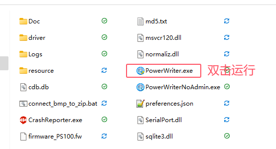
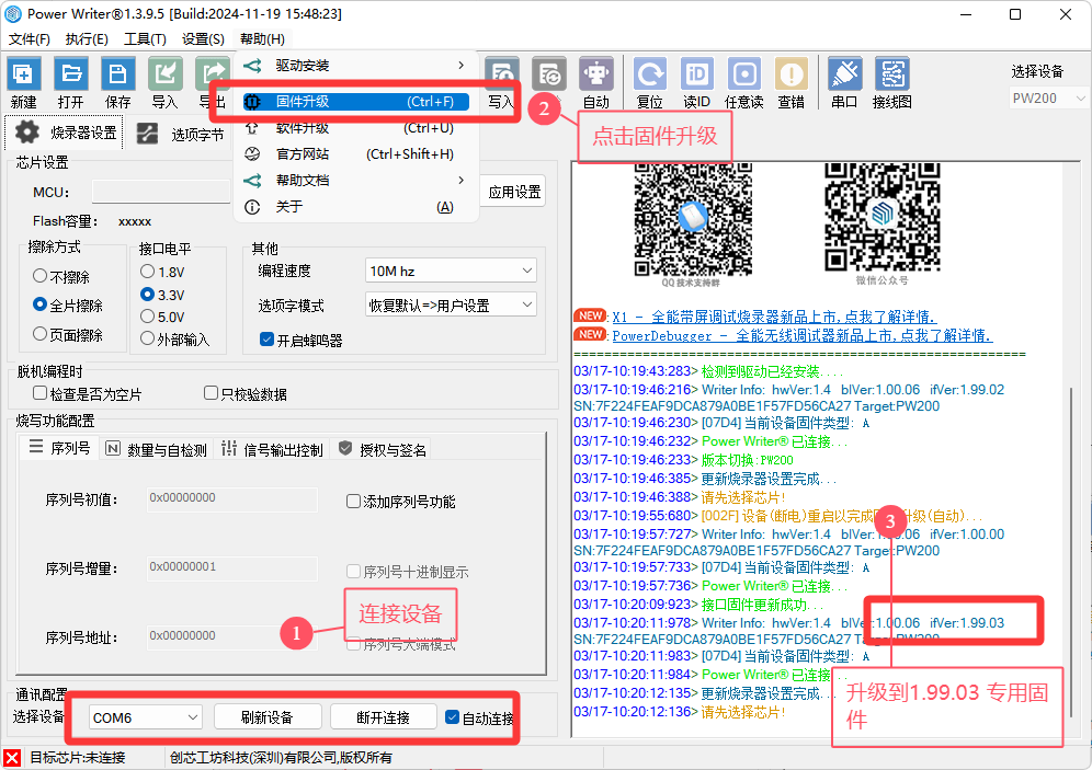
2.1 Upgrade firmware
Upgrade the firmware to 1.99.03 or above, and make a special e-cigarette firmware.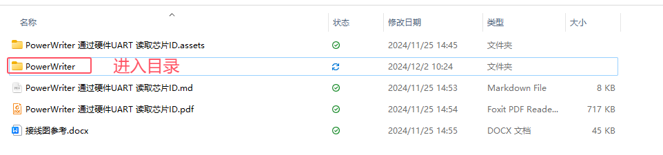
2.2 Engineering Settings and Wiring Diagram Reference
2.2.1 Device power supply mode
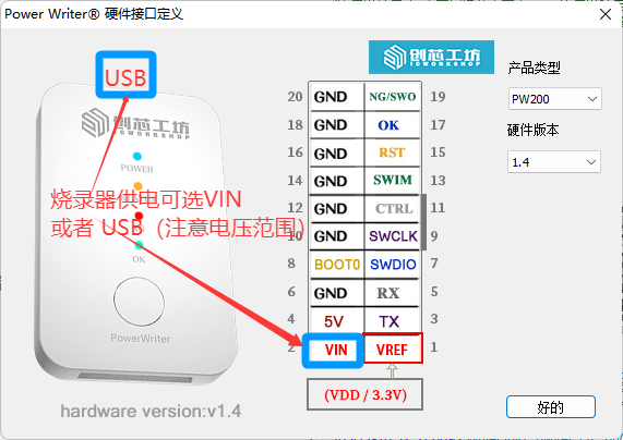
When choosing to supply power to the device from VIN, please pay attention to the voltage range:3.3V~5.5V When it exceeds 5.5V, the device may be damaged, and when it is below 3.3V, the device may not work.
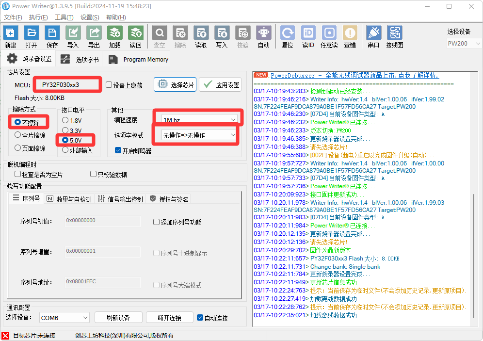
2.2.2 Project setting reference and wiring
Chip model : PY32F030xx3 .
Erase Type: Choose not to erase, to avoid accidental erasure of e-cigarettes.
Interface level:
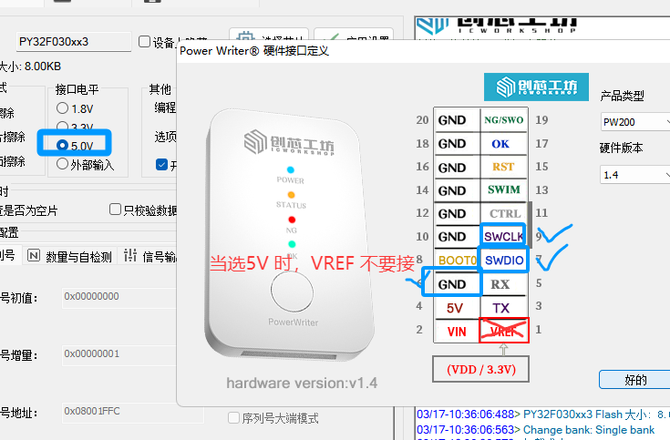
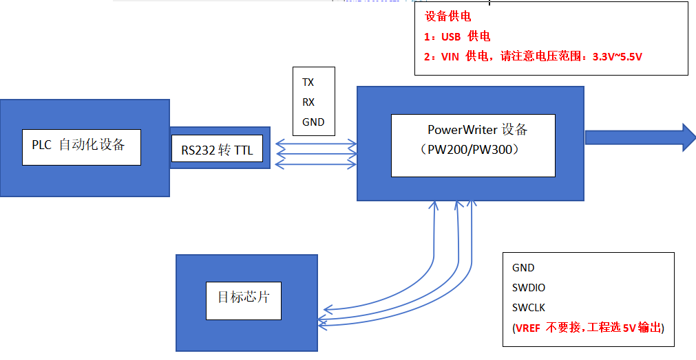
Mode 1 (Promotion):Select 5V, and programming device's VREF is not connected, as shown in the following figure:
Mode 2 (When mode 1 cannot read the ID): Select external input, and connect the power supply ports connected to the electronic cigarette, as shown in the following figure:
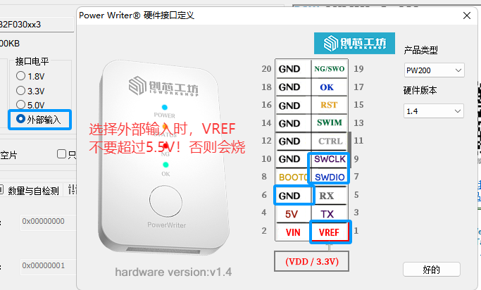
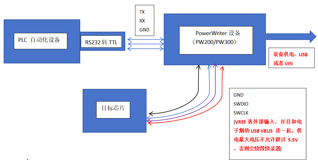
When selecting external input, please connect it with the USB power supply of electronic cigarette, and the voltage should not exceed 5.5V, and it is better not to exceed 5.3V because of the tolerance of electronic components. Otherwise, it may cause fever or affect the service life (there is a voltage regulator inside) due to the error of components. Do not connect it with 12V or 24V, or it will burn programming device because it exceeds the design load capacity of programming device.
Programming speed:Choose 1Mhz.
OptionByte:Nop=>Nop.
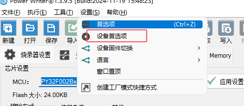
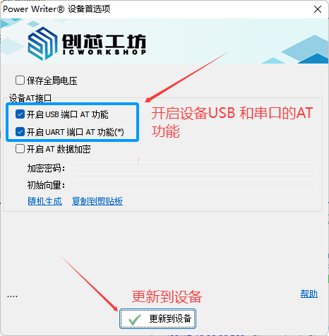
2.3 Enable AT function and load project.
Turn on the AT function in the menu bar, settings and device preferences.
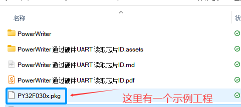
2.4 Load items to devices
After selecting the chip, load the blank project into the device, as shown below:
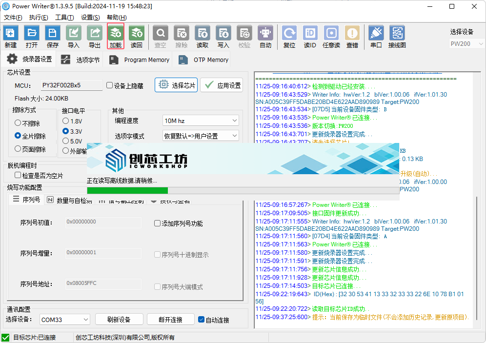
Because only the chip ID needs to be read, only an empty project is needed, and there is no need to add data.
3. Open source AT API access
3.1 Simplified process of testing
3.1.1 Read the target chip ID
Call powerwriter_at_target_ID to send the command to read the target chip ID. If the reading is normal, it will return the command of ATCmdRspTargetChipID, and if it fails, it will return the command of ATCmdStatusError.
Read the target chip ID (when unencrypted):
//50 57 41 54  18 00 00 00  66 00 00 00    04 00 00 00  00 00 00 00  d3 b7 4e 74
//   固定头部  |   帧长度     |0x66为读取ID  | 0x04命令长度 |  命令保留值  |   crc32   |
The return value is ATCmdRspTargetChipID or ATCmdStatusError (when unencrypted):
#define PW_TARGET_ID_MAX 16              // Target chip ID MAX size
typedef struct S_ATCmdRspTargetChipID
{
    uint8_t m_CIDSize;                   // Target chip ID size
    uint8_t m_CIDData[PW_TARGET_ID_MAX]; // Target chip ID data
} S_ATCmdRspTargetChipID;

/* ATCmdRspTargetChipID */
/*
 50 57 41 54  25 00 00 00  67 00 00 00           11 00 00 00    10    32 30 53 41 13 33 32 33 33
  固定头部    |   帧长度    |ATCmdRspTargetChipID |  0x11 命令长度|ID 长度|ID 值
 22 6e 10 78 b1 01 56   84 6b 94 1e
                      |   CRC32     |
*/
/* Get target id */
S_ATCmdRspTargetChipID m_target_id;
if (!powerwriter_at_target_id(channel, &m_target_id))
{
    powerwriter_at_log(LOGE, "[%08X]:powerwriter get target id failure ...\r\n",
                       powerwriter_at_last_error(channel));
    return false;
}
object_print(m_target_id.m_CIDData, m_target_id.m_CIDSize, "Target chip id");
powerwriter_at_log(LOGD, "powerwriter get target id successfully ...\r\n");
3.1.2 Reading target chip data(Version information)
Depending on the read address and length, the CRC32 of the instruction is not fixed. You can copy the received and sent data through the sample of the source code, or contact the technical support of ICWorkshop to help give the hexadecimal sequence.
Call powerwriter_at_target_read to send a command to read the data of the target chip. If the reading is normal, the command of ATCmdRspTargetMemory will be returned, and if it fails, the command of ATCmdStatusError will be returned (see the previous section for the structure).
Read the target chip ID (when unencrypted):
//固定头部(4)  | 帧长度(4)   |0x68为读芯片数据|0x08命令长度|  读取地址  |  读取长度    |   crc32   |
//50 57 41 54  1c 00 00 00  68 00 00 00  08 00 00 00  00 10 00 20  02 00 00 00  62 dd 55 8b //从0x20001000读取2字节
//50 57 41 54  1c 00 00 00  68 00 00 00  08 00 00 00  00 10 00 08  20 00 00 00  12 de df 70 //从0x08001000读取32字节
//50 57 41 54  1c 00 00 00  68 00 00 00  08 00 00 00  20 10 00 20  20 00 00 00  81 d8 18 78 //从0x20001020读取32字节
The return value is ATCmdRspTargetMemory or ATCmdStatusError (when unencrypted):
#define PW_PACKAGE_SIZE 256                     // Buffer size of block data
typedef struct S_ATCmdTargetMemory
{
    uint32_t m_address;                // Current data address
    uint32_t m_size;                   // Current data size
    uint8_t m_buffer[PW_PACKAGE_SIZE]; // Current data buffer (fixed length)
} S_ATCmdRspTargetMemory,

/* ATCmdRspTargetMemory */
/*
  50 57 41 54   //固定头部
  1c 01 00 00   //帧长度
  69 00 00 00   //69 表示返回数据
  08 01 00 00   //0x108 标识数据长度
  00 10 00 20   //表示读取的地址为 0x20001000
  02 00 00 00   //表示读取的数据长度

  //下面表示256 字节的缓冲区,有效数据是前两个
  ba 8c 33 43 46 37 43 45 43 42 45 30 34 30 36 44
  32 45 37 32 31 46 38 42 31 35 32 43 30 31 34 32
  31 2e 34 00 00 00 00 00 31 2e 30 30 2e 30 36 00
  31 2e 30 31 2e 33 32 00 b2 d1 0a 6b e7 40 1a ed
  e7 30 b5 68 4b 00 21 68 4c 4b 44 19 70 0a 46 7c
  44 55 00 65 5b 85 42 00 d1 01 21 52 1c 02 2a f7
  d3 19 70 00 29 01 d0 00 20 30 10 b5 00 23 02 e0
  cc 5c c4 54 5b 1c 93 42 fa d3 10 bd 10 b5 00 22
  ff 23 03 e0 4a 29 04 d0 83 54 52 1c 8a 42 f9 d3
  10 bd 84 18 40 34 e4 7f 84 54 f6 e7 40 1a ed e7
  30 b5 68 4b 00 21 68 4c 4b 44 19 70 0a 46 7c 44
  55 00 65 5b 85 42 00 d1 01 21 52 1c 02 2a f7 d3
  19 70 00 29 01 d0 00 20 30 bd 01 20 30 bd f0 b5
  5c 4c 16 46 0f 46 05 46 4c 44 00 2b 18 d0 5b 48
  57 4a e0 60 00 20 4a 44 90 32 2b 5c 11 18 4b 70
  3b 5c 40 1c 4b 74 10 28 f7 db 51 48 4b 22 48 44

  b0 07 eb 06 //命令的CRC32
*/
Send and receive data can be captured and analyzed by demo.
    #ifdef AT_ONLINE_READ_DATA_SAMPLE
    // example is G32F350xB ,128 KB Flash & 16K sram
    int i = 0;
    powerwriter_at_log(LOGD, "powerwriter read target memory starting ...\r\n");
    S_ChipMemoryCfg m_chip_memory[] = {
        {.m_s_addr = 0x20001000,
         .m_e_addr = 0x20001002,
         .m_name = "2byte SRAM"},
        {.m_s_addr = 0x08001000,
         .m_e_addr = 0x08001020,
         .m_name = "32 byte Flash"},
        {.m_s_addr = 0x20001020,
         .m_e_addr = 0x20001040,
         .m_name = "32 byte SRAM"},
    };
    S_ATCmdRspTargetMemory *mem = 0;
    for (i = 0; i < ARRAY_SIZE(m_chip_memory); i++)
    {
        uint32_t addr = m_chip_memory[i].m_s_addr;
        do
        {
            int read_size = MIN(PW_PACKAGE_SIZE, m_chip_memory[i].m_e_addr - addr);

            if (!powerwriter_at_target_read(channel, addr, read_size, &mem))
            {
                powerwriter_at_log(LOGE, "[%08X]:powerwriter read target memory failure ...\r\n",
                                   powerwriter_at_last_error(channel));
                return false;
            }
            powerwriter_at_log(LOGD, "(%s)memmory addr: 0x%08X, memory size: %d\r\n", m_chip_memory[i].m_name,
                               mem->m_address, mem->m_size);
            object_print(mem->m_buffer, mem->m_size, "data block:");
            addr += mem->m_size;
        } while (addr < m_chip_memory[i].m_e_addr);
    }
    powerwriter_at_log(LOGD, "powerwriter read target memory test passed ...\r\n");
#endif
3.1.3 Write SRAM data
Because the execution of the chip will be suspended when reading the chip ID, it is necessary to reset the function of the product after connecting and reading the CID, otherwise it may be necessary to power off the device or manually restart the device to restore the function of the product(For example, e-cigarettes don't smoke).
Reset target chip (when unencrypted):
// 口数清零 puff   操作 0x20001000-0x20001001  共 2个byte
50 57 41 54     1e 00 00 00  6d 00 00 00  0a 00 00 00   00 10 00 20  02 00 00 00  00 00   2c 52  b4 c5
//   固定头部  |   帧长度     |0x6d 为写数据| 0x0a命令长度  |  写入地址   |   写入长度   |  写为0  | crc32
The return value is ATCmdStatusOk or ATCmdStatusError (when unencrypted), Refer to the error code when connecting the chip.
3.1.4 special explanation
Reading and writing different addresses is different from crc32. If you don't know the value, you can consult technical support to get the instruction sequence, or grab the data based on the open source library of AT code.
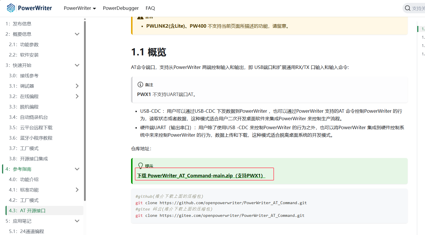
3.2 PowerWriter® Open source AT code
Reference document address: 4.3:AT 开源接口 | PowerWriter®文档中心 Download the source package, as shown in the following figure:
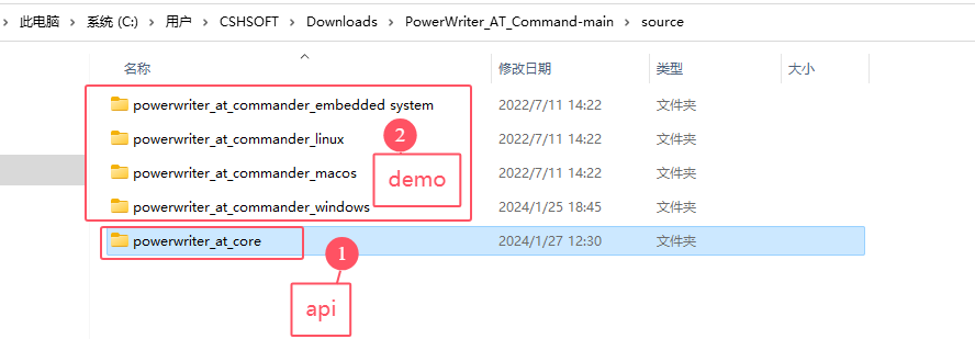
After downloading and decompressing, you can see the following directory, in which the source directory has cross-platform API source code:
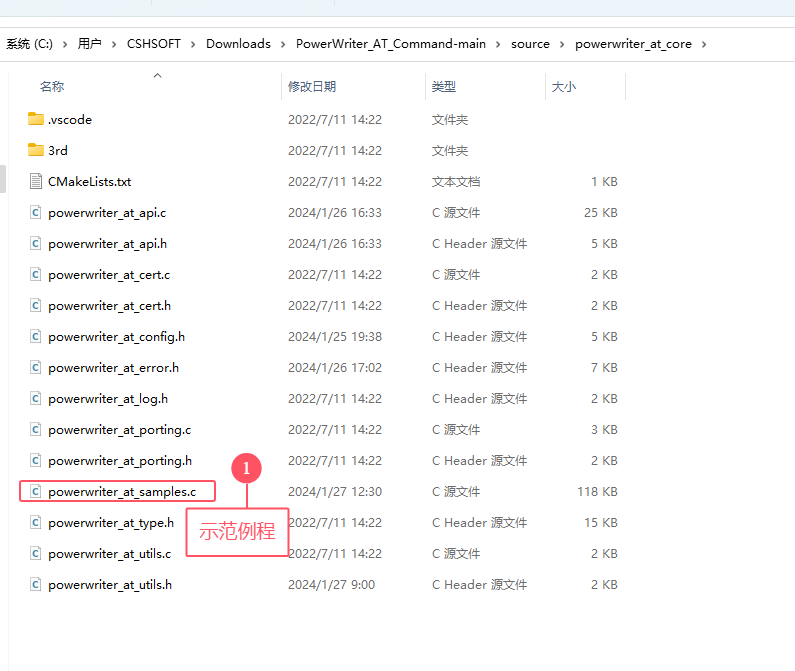
Powerwriter_at_core is a cross-platform implementation, which can run on almost all platforms only by adapting serial port transceiver and timestamp implementation interface. Currently, the demo provided is windows version, and other platforms have not provided demos yet, so you can refer to powerwriter_at_samples.c for implementation.
4. Matters need attention
4.1 About the Default Communication Baud Rate
The default baud rATe of the at port of is 9600. When the PowerWriter® client is connected, the baud rate of the at port will become 115200. When the PowerWriter® client is disconnected, the baud rate will return to the default 9600. If communication is not possible, please re-power the PowerWriter® device and try again.
Please pay attention to the baud rate of communication.
4.2 About device power supply and VREF voltage range
Please pay special attention to: the safe power supply range of VREF and VIN and USB should not exceed 5.5V (design limit), otherwise, programming device may be damaged or the service life of programming device may be shortened.