2.1 Functional parameters
2.1.1 Summary
PW400 is the version of PowerWriter series RISC-V, which supports debugging of RISC-V series chips (Nuclei kernel), as well as in-circuit programming of RISC-V series chips, offline programming, machine burn-in and other functional features.
LCM 8051 series chips are supported on PW400 series at the same time.
2.1.2 Parameters
- Size : 92.000mm 56.000mm 16.000mm
- Operating voltage : DC5V
- Power Consumption: 30mA@5V~100mA@5V
- Driving ability: 5V@700mA (Max)
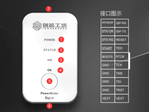
2.1.3 Signal description
The PowerWriter interface is a mix of burner station signals, standard serial port signals, BOOT0 control, and power supply (the power supply supports outputs of 1.8V, 3.3V, 5.0V, and can also be used as an input reference to the PowerWriter logic levels), as illustrated in Section 2.1.2.
| Pin Name | Pin Function |
|---|---|
| VEXT (VREF) | Target chip VDDIO reference voltage |
| GND | Power Ground Wire |
| TRST | JTAG TAP Reset Control |
| TDI | JTAG TDI Data Line |
| TMS | JTAG TMS Mode Selection Line |
| TCK | JTAG TCK Clock Line |
| RTCK | JTAG RTCK Reference Clock |
| TDO | JTAG TDO Data Line |
| RESET | Chip's Reset pin |
| ISP_TX | Standard serial port, ISP burn-in, etc. |
| ISP_RX | Standard serial port, ISP burn-in, etc. |
| BOOT0 | BOOT0 boot mode can be controlled |
| STA-BUSY | Offline busy output (output high) |
| STA-OK | Offline successful output (high output) |
| STA-NG | Offline Failure Output (Output High) |
| START | Machine start signal (low pulse start) |
VEXT is the target chip's IO reference voltage (VDDIO), alias VREF, which can be set to 1.8V, 3.3V, 5.0V, or external reference input.
2.1.4 State Definition
| Signal Name | Signal Description |
|---|---|
| POWER LED | Always on at power-up. |
| STATUS LED | Lamp does not light up during power-on without operation. |
| Blinks when communicating with the application software, the blinking frequency follows the communication speed setting. | |
| Blinking during offline burning, blinking frequency follows the communication speed setting. | |
| When connected to the target chip, it will always light up. | |
| NG LED | Lights up when there is an operation error, or when an operation such as reading, erasing, or programming fails, and goes out until a new operation is performed. |
| OK LED | Lights up when a read, erase, program, etc. operation is successful and goes out when a new operation is performed. |
| Buzzer Frequency Definition | The PWM frequency is 2.7K Hz (defined below). |
| Buzzer count definition | Beep sound at power-on without operation. |
| One beep when the target chip is connected. | |
| Two beeps when programming is successful or downloading offline files is successful. | |
| Three beeps when the operation fails. | |
| When the offline programming count is 0, four ticks are heard. | |
| Button | Effective for offline programming (release trigger, ignore long press for longer than 1S). |
| OK signal | Output high when offline operation is successful, clear 0 when there is a new operation. |
| NG signal | Output high when offline operation fails, clear 0 when new operation is performed. |
| BUSY signal | Output high when offline is being programmed. |
| START signal | Input a low signal >= 40ms to initiate an offline programming. |
2.1.5 Characteristics
- On-line data programming (read/write)
- Online option byte programming (read/write)
- Online Data Export
- Online Target Chip Checker
- In-line target chip erase (full chip erase, custom sector erase)
- Online calibration of chip data.
- On-line automatic programming
- In-line reset target chip
- Online read-protect write (remove)
- Reset target chip data online
- On-line reading of arbitrary data from the target chip
- Option byte operation modes (four modes)
- Check Chip ID online
- VREF settable (1.8V, 3.3V, 5.0V, external reference)
- Adjustable programming speed
- Serial Number Function
- Offline times limit
- Offline auto start/stop
- Automatic operation control after programming
- Firmware signature (ICWKEY, Matrix)
- Machine programming support
- Cloud Platform Support
- Debugger
- Serial Assistant
- Other cumulative 400+ functional features
The features listed above are typical, but please refer to the PowerWriter User's Manual for more information.
For product differences, please see PowerWriter product selection