3.4.4.2:SPI&MWEEPROM
1: Introduction
PowerWriter® supports manufacturer-specific functions using a plugin mode, which can accommodate any special requirements from different manufacturers. The access method is consistent with other brand support methods. After selecting the chip, if a plugin support icon appears on the far right of the toolbar, it indicates that the currently selected chip has plugin support functions, as shown below.
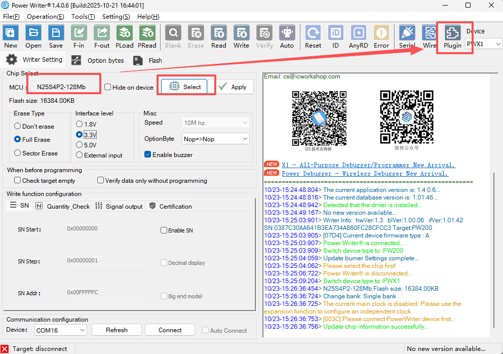
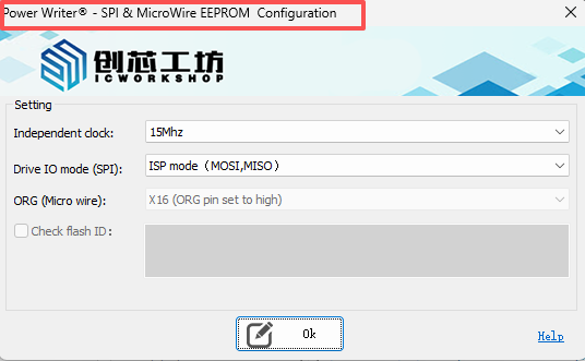
After selecting a chip from the SPI & MicroWire EEPROM series, an extension function button appears on the right side of the toolbar, defined as the manufacturer-specific plugin function. Click this button to enter the SPI & MicroWire EEPROM configuration page, as shown in the following figure:
2.Settings
2.1 Programming Clock
The programming clock determines the communication clock frequency between the device and the EEPROM. Selecting an appropriate frequency ensures programming stability and speed.
Available frequencies:
- 1 MHz: Low speed, suitable for long cables or environments with strong interference.
- 1.875 MHz
- 3.75 MHz
- 7.5 MHz
- 15 MHz: Default is 15MHz
- 30 MHz: High speed, suitable for short-distance, high-quality connections.
2.2 Drive Mode (SPI Drive Mode)
The drive mode determines the signal line configuration used for SPI communication.
Available modes:
- ISP Mode (MOSI/MISO) Standard SPI communication method, suitable for the vast majority of SPI EEPROM chips, especially smaller capacity, older model chips.
- Quad Mode (IO0, IO1, IO2, IO3) Uses four bidirectional data lines, typically used for EEPROMs supporting high speed or specific protocols.
Note: Please select the correct drive mode according to the EEPROM chip manual you are using. If the ISP mode works but is slow, you can try switching to Quad Mode, provided the chip supports it and the four IO lines (IO0-IO3) are connected on the hardware.
2.3 ORG Pin Setting (ORG Pin)
The ORG pin on Micro Wire SPI EEPROM chips is used to organize the sector structure of the Flash.
Available settings:
- X16 (ORG pin set to high) Sets the EEPROM to 512 x 16 sectors.
- X8 (ORG pin set to low) Sets the EEPROM to 1k x 8 sectors.
The ORG pin is driven by the BOOT0 pin, set it high or low. For the rest of the connection methods, please refer to the Micro Wire connection diagram and the chip datasheet to confirm whether it should be set to X8 or X16.
2.4 Check ID (SPI)
This option is used to verify whether the device can correctly identify the EEPROM's manufacturer and device ID before programming.
- Checked: Automatically performs ID check before programming.
- Unchecked: Skips the ID check and proceeds directly to programming.
3: Usage Steps
Connect the PowerWriter® to the target EEPROM.
Set the Programming Clock, Drive Mode, and ORG Pin according to the chip manual.
It is recommended to check "Check ID" to confirm correct chip identification.
Click "Auto" to start online programming or start offline programming.