3.3 ECDSA Sample
3.3.1 Prepare
ECDSA signature is an asymmetric encryption electronic signature method, the private key is stored in the signature device ICWKEY, and the public key is stored in the project firmware. ICWKEY generates the signature information through the ID of the target chip and the current private key, and then writes the signature information to the specified address of the firmware through the PowerWriter®, and during the operation of the firmware, it verifies whether the signature information is valid through the public key + ID, thus determining whether the current chip has been validly authorized, and avoiding the firmware from being directly copied. When the firmware is running, the public key + ID will be used to verify whether the current signature information is valid or not, so as to determine whether the current chip has been validly authorized, and to avoid the firmware from being directly copied and used. Before we start, we need to follow the process of verifying that all the preparatory work has been completed.
- ICWKEY signatures (or ICWKEY signature lock mode) are used in PowerWriter® projects.
- The signature address has been set (e.g. 0x08002000).
- The communication information on the PowerWriter® side has been synchronized to the project in ICWKEY and encrypted communication with the project has been re-established.
- Reasonably set the number of times it can be authorized, for example, set it to 10,000.
- Signature method: ECDSA signature was chosen, saved to ICWKEY, and the source code was exported.
If all the above steps are completed, you can see the display information of ICWKEY device and the exported source code information, refer to the following:

At the same time the ICWKEY device will display the following message:

3.3.2 Sample project
3.3.2.1 Prepare
Sample project path ICWKEY installation path, specifically:
C:\Users\用户名\AppData\Local\ICWKEY\Examples_for_mdk
ICWKEY desktop icon, you can quickly locate until, and copy the ECDSA sample project to the specified path, and decompression, reference demo as follows:

3.3.2.2 Code structure
3.3.2.2.1 startup_stm32f103xg.s
- 调整堆大小 > 0x1300
- 挑战栈大小 > 0x800
Stack_Size      EQU     0x1000      ;Please make the stack bigger, ECDSA signature verification needs more stack space!

                AREA    STACK, NOINIT, READWRITE, ALIGN=3
Stack_Mem       SPACE   Stack_Size
__initial_sp

; <h> Heap Configuration
;   <o>  Heap Size (in Bytes) <0x0-0xFFFFFFFF:8>
; </h>

Heap_Size      EQU     0x2000       ;Resize heap > 0x1300 for dynamic memory allocation

                AREA    HEAP, NOINIT, READWRITE, ALIGN=3
__heap_base
Heap_Mem        SPACE   Heap_Size
__heap_limit

                PRESERVE8
                THUMB
Please pay special attention to the stack size, to adjust it, otherwise it will not be able to perform the signature verification and return an out of memory error message.
3.3.2.2.2 cortex_chipid_binding.c
- Replace the public key with the one exported by ICWKEY.
//Use the public key in ICWKEY for substitution.
const static uint8_t PUBLIC_KEY[49]={
    0x04,0x00,0x7F,0xFE,0xF3,0x5A,0xFB,0x48,0xC3,0xEB,0xE8,0xE5,0x41,0xDE,0xAF,0x99,
    0x89,0x48,0x8C,0x31,0x93,0x2A,0x91,0x81,0xD1,0x17,0x62,0xA5,0x89,0xA6,0x77,0x02,
    0x14,0x60,0xC7,0x79,0x1E,0x33,0xDF,0x8F,0xE0,0xF0,0xC2,0x47,0x03,0x49,0x7B,0x5F,
    0xF7
};
3.3.2.2.3 cortex_chipid_binding.h
- Fill in the ID address (see prompt message)
- Change the signature address to the signature address in PowerWriter®.
- Depending on the situation, whether placeholders are turned on or not.
/* Exported define --------------------------------------------------------*/
/* The following parameter definitions must be consistent with the actual chip and burner settings */

#define    UID_CHIP_MASK                0xEF2A7BF1              //Random generation
#define    UID_CHIP_SIZE                12                      //ChipID Size                                  //ChipID Size
/* ID address of the target chip, which can be queried according to the chip's manual */
#define    UID_CHIP_ADDR                (0x1FFFF7E8^UID_CHIP_MASK) //ChipID Inner Addr in chip

//Signature information storage address, change to the address where the signature information is stored in the PowerWriter® project 0x08002000
#define    LICENCE_ADDR                 (0x08002000^UID_CHIP_MASK)  //Licence Store Addr In flash

/*
    Description:
    This customisation is used to decide whether to placeholder (pre-allocate) the signature information in the firmware, to prevent overlapping with other function addresses, PowerWriter® may accidentally erase the code when burning
    PowerWriter® may accidentally erase the code when burning and cause problems with the firmware, in this case, it is necessary to pre-allocate, so if the flag bit is 0, it means no placeholder, in this case, it is necessary to store the storage address of the signature information, stored outside the firmware.
    Summary:
    1: The signature address is within the actual firmware range, the placeholder must be turned on;The signature address is outside the actual firmware range, it is recommended not to open the placeholder to avoid the firmware is too large.
  2:If the address exceeds 0.7 chip capacity, the placeholder is not turned on, and if the address is less than 0.7 chip capacity, the placeholder is turned on.
*/
#define    UID_LICENCEADDR_PLACEHOLDER_EN   1                    //Licnece Store Addr In Flash Enable/Disable Placeholder
UID_CHIP_ADDR address, you can use PowerWriter® to select the signature mode as Matrix, export the source code can see the actual ID address.
3.3.2.2.4 main.c
- Initialization ID
- Verify Signature
/* Private user code ---------------------------------------------------------*/
/* USER CODE BEGIN 0 */
//Used to print log messages from the serial port
int fputc(int ch, FILE *f)
{
        uint8_t ch8 = (uint8_t)ch;
        HAL_UART_Transmit(&huart2,&ch8,sizeof(ch8),5);
        return (ch);
}
/* USER CODE END 0 */

/**
  * @brief  The application entry point.
  * @retval int
  */
int main(void)
{
  /* USER CODE BEGIN 1 */

  /* USER CODE END 1 */


  /* MCU Configuration--------------------------------------------------------*/

  /* Reset of all peripherals, Initializes the Flash interface and the Systick. */
  HAL_Init();

  /* USER CODE BEGIN Init */

  /* USER CODE END Init */

  /* Configure the system clock */
  SystemClock_Config();

  /* USER CODE BEGIN SysInit */

  /* USER CODE END SysInit */

  /* Initialize all configured peripherals */
  MX_GPIO_Init();
  MX_TIM1_Init();
  MX_USART2_UART_Init();        // Serial port initialisation for log printing
  /* USER CODE BEGIN 2 */
  //Initial Chip
  ChipUIDInitial();             //Signature initialisation, used to initialise chipid, for chips with non-consecutive IDs, please copy consecutively, please check code
  /* USER CODE END 2 */

  /* Infinite loop */
  /* USER CODE BEGIN WHILE */
  while (1)
  {
    /* USER CODE END WHILE */

    /* USER CODE BEGIN 3 */
        //Check in your code
      if(ChipUIDAlgo_Check())       //Verify the signature
        {
           //ok:LED
             HAL_GPIO_TogglePin(LED1_GPIO_Port, LED1_Pin);
             HAL_GPIO_TogglePin(LED2_GPIO_Port, LED2_Pin);
             HAL_Delay(100);
      }
      else
      {
           //false: LED
           HAL_GPIO_WritePin(LED1_GPIO_Port, LED1_Pin, GPIO_PIN_RESET);
           HAL_GPIO_WritePin(LED2_GPIO_Port, LED2_Pin, GPIO_PIN_RESET);
      }

  }
  /* USER CODE END 3 */
}
The sample code is just a demo, for more security, please note that hiding the code can improve the security, if necessary, contact us to get the MCU Common Security Protection Library to further enhance the firmware security and prevent the firmware from being reverse decompiled, cracked, and modified.
3.3.2.3 Compiling
#define SISSDK_LOG_ENABLE //disbale /Enable #warning You have to implement fput functions to use log print function
Logging can be turned on during verification for easy viewing of the results. Compile the project and the test firmware will be generated in the directory Output\TargetIC_Example.bin.
3.3.2.4 Validate
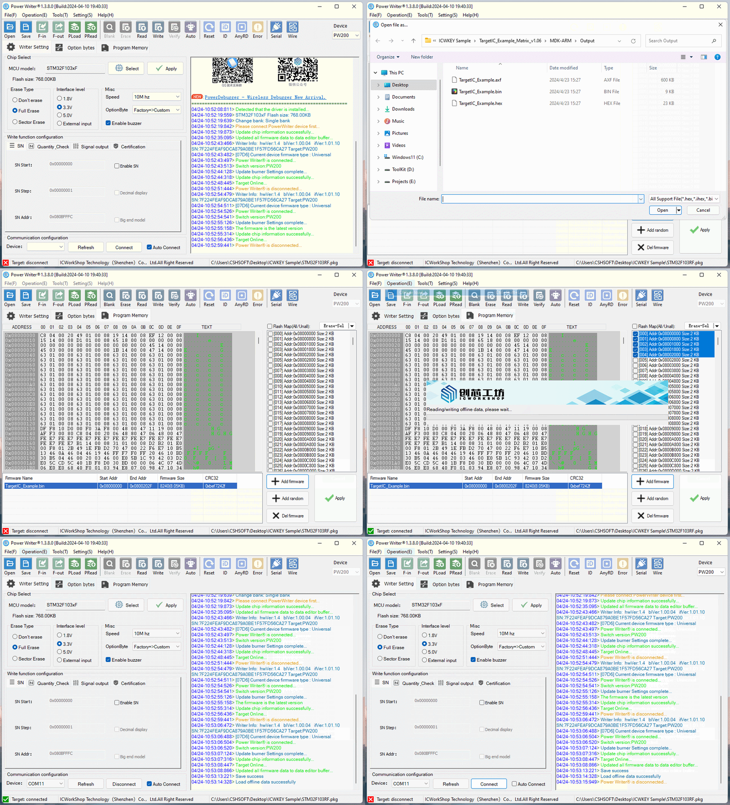
Reopen the PowerWriter® project, add the TargetIC_Example.bin test firmware to the Program Memory page, and load the project into the PowerWriter® device as shown below:

Connect ICWKEY to PowerWriter®, and connect the target PCB of MCU to be programmed, and connect the power supply for programming, the reference wiring is shown as follows.
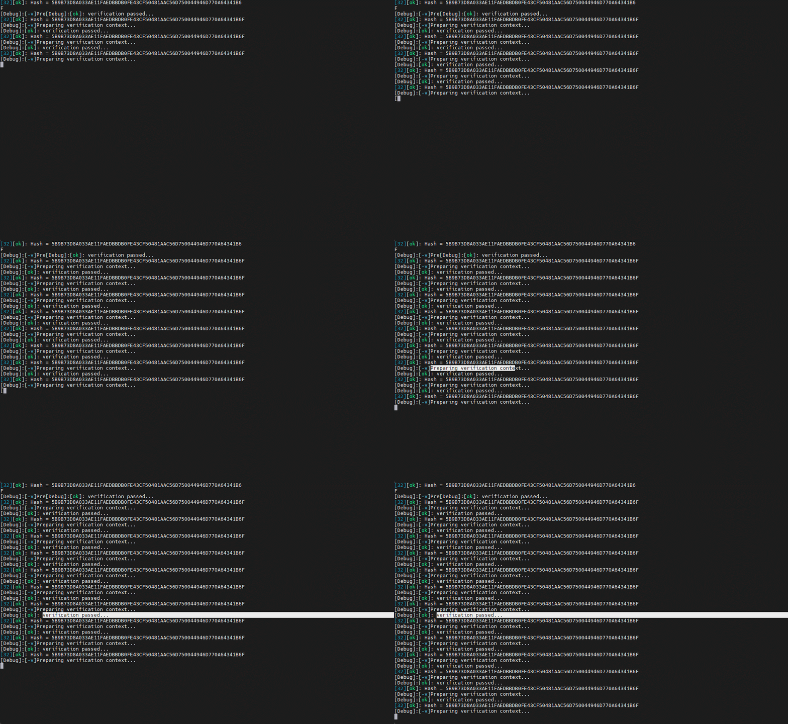
After programming, connect the serial port TX pin of the target PCB, you can see the output signature verification information, refer to the following:

3.3.2.5 Debugging method
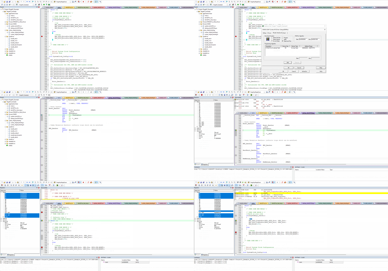
After using PowerWriter® to sign the target firmware and program it to the target chip, you can check whether the signature is in effect by setting the status output. In complex scenarios, you can't determine the location of the problem simply by looking at the working status, and at this time, you need to debug the target chip, and the debugging steps are as follows:
- Refer to the compilation and verification process to complete the programming
- IDE selection: proceed without erasing the target chip, without programming the target chip, and without verifying the target chip.
The reference demo is shown below:
