5.2 AT Application Examples
- PWLINK2 (including Lite), PW400 Please note that the functions described on the current page are not supported.
- To use the AT function, you need to enable AT mode on the device first, refer to Device Preferences.
This section describes in detail the software system associated with the PowerWriter® AT GUI, which can be used as a guide to the software, or as a reference manual, and can be consulted at any time if you do not understand something.
Software Download URL:
PowerWriter -> Downloads -> Client -> PowerWriter AT Application
1 PowerWriter® AT GUI Main Interface
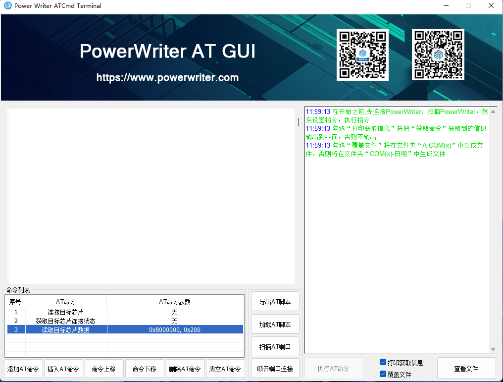
The startup screen of the PowerWriter® AT GUI application is shown in Figure 1.1.1 below.
2 PowerWriter® AT GUI Features
2.1 Add command
The command selection screen pops up, as shown in Figure 1.1.1.1 AT command selection screen

Mouse click on the specified AT command, the corresponding command will be added to the command list, if the command has parameters to be set, the command list of the "AT Command Parameters" column will be prompted to "double-click on the mouse to set or modify the parameters", if you need to modify the AT commands, double-click on the "AT Command" column can be, the following figure 1.1. 1.2 Command List
2.2 Insert AT command
Inserts an AT command above the selected line.
2.3 Command Up
Moves the selected line AT command to the previous line.
2.4 Command Down
Moves the selected line AT command to the next line.
2.5 Delete AT command
Removes the selected line AT command.
2.6 Clear AT command
Clear the AT command from the command list.
2.7 Exporting AT Scripts
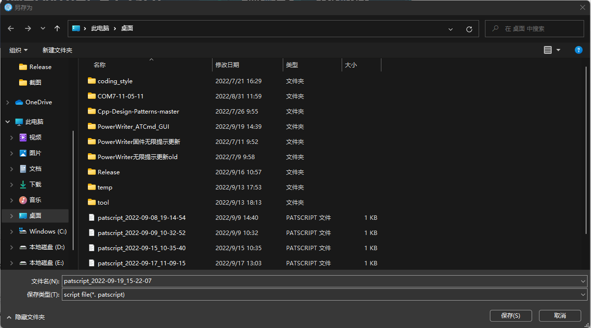
The AT commands in the command list are exported as AT scripts. The default file name is "patscript year-month-day hour-minute-second" and the file extension is: ".patscript", which is common to the command line version, as shown in Figure 1.1.1.3 AT script file export below
2.8 Loading AT Scripts
Import the selected AT script file into the command list.
2.9 Scanning AT ports
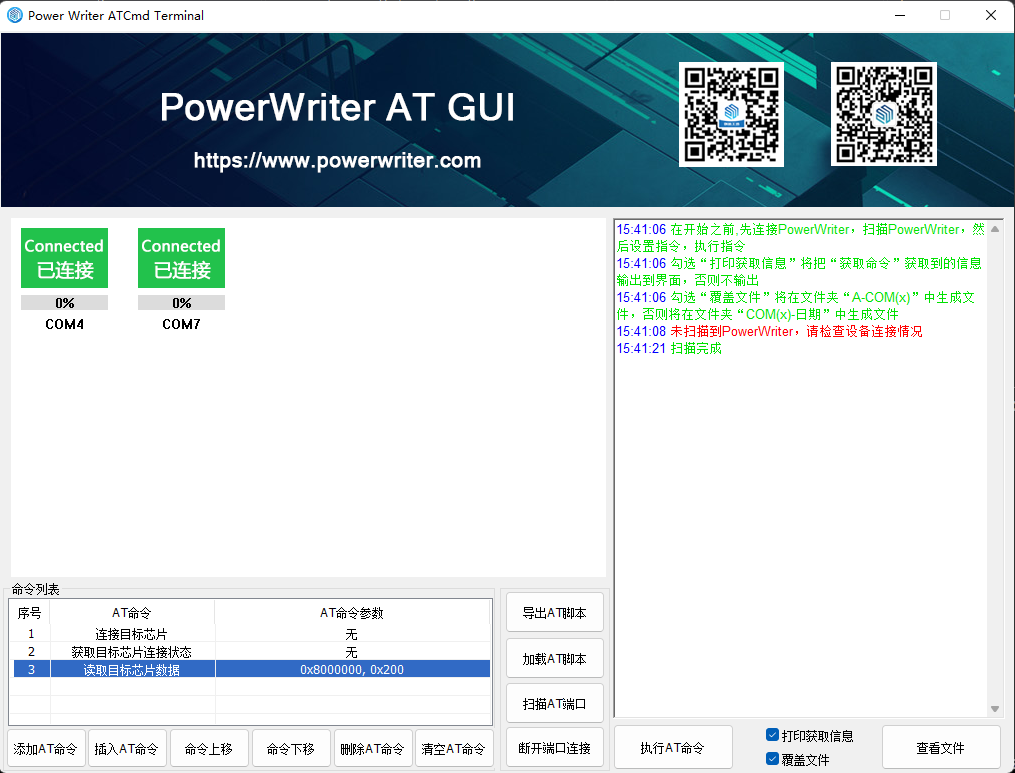
Scan the PowerWriter® with "USB port AT function" enabled, and display the scanned port on the software interface, if the device is not scanned, it will prompt "PowerWriter® is not scanned, please check the connection of the device", as shown in the following figure 1.1.1.4 AT port
2.10 Disconnecting the port
Disconnect all ports as shown in Figure 1.1.1.5 Disconnecting Ports below

2.11 Execute the AT command
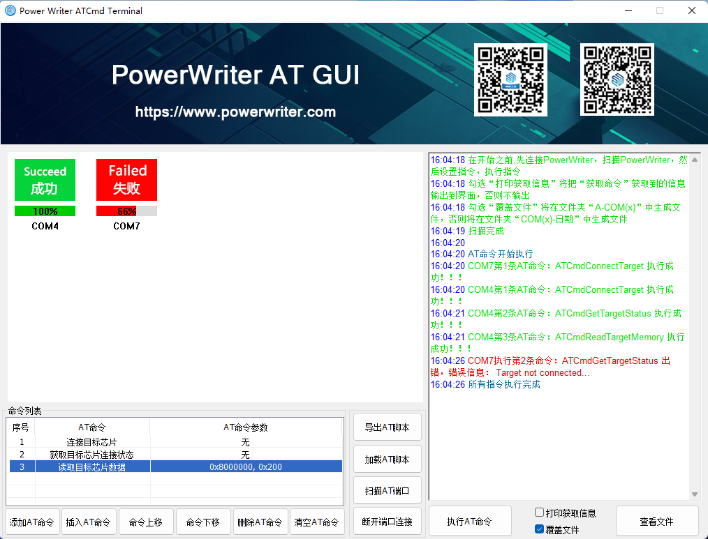
Each connected port executes all the commands in the command list concurrently in multiple threads, and prints the execution result after each command is executed, and the corresponding port will stop executing the command and report an error if there is an error in the execution of the command. As shown in the following figure 1.1.1.6 Command Execution
2.12 Print Info
Checking "Print the information" will output the information obtained by "Get Command" to the interface, otherwise, it will not be output.
2.13 Overwrite the file
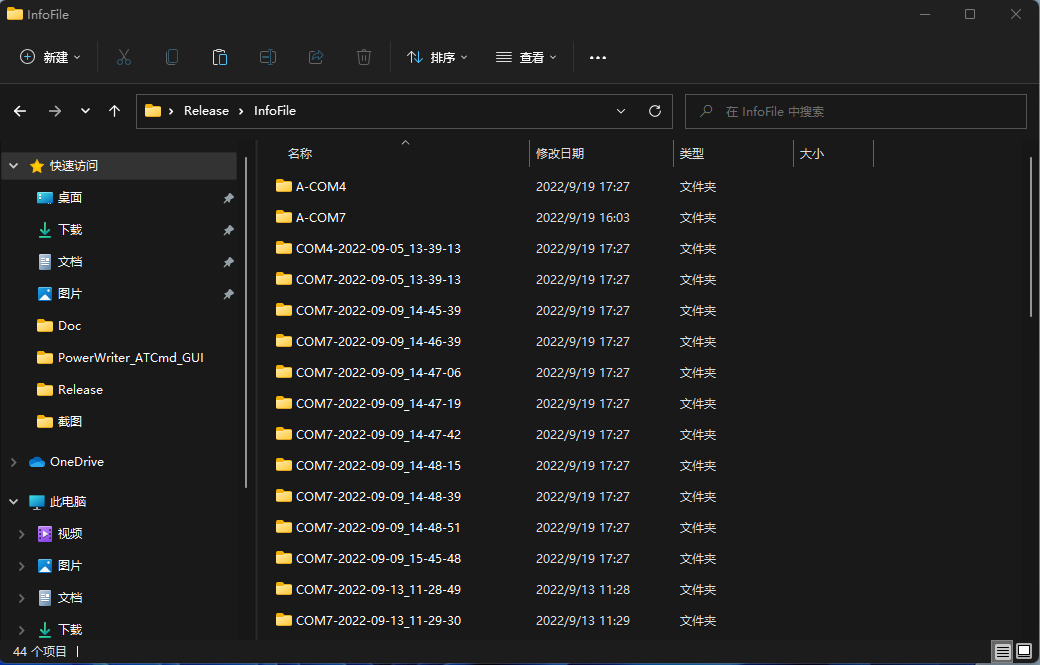
Tick "Overwrite file" to generate the file in the folder "A-COM(x)", otherwise the file will be generated in the folder "COM(x)-Date" as shown below. 1.1.1.7 Viewing the file is shown.
2.14 View Document
The "Get Command" will save the acquired data to a file, the file path is Info\A-COM(x) or Info\COM(x)-Year-Month-Day_Hour-Minute-Second, click the "View File" button to view the file generated by the Get Command. Click the "View File" button to view the file generated by the command, please refer to the following figure 1.1.1.7 View File
3 Parameter setting interface
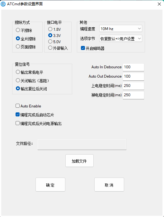
Double-click the "AT Command" column, if the command needs to set parameters, the parameter setting interface will be popped up, and different commands will display different parameters, Note: If the AT command is to update the "PW Configuration", it will also save the configurations as a json file, the path of which is in the root directory of the software, /writer_cfg.json. The following figures are shown in Figures 1.2.1 and 1.2.2.
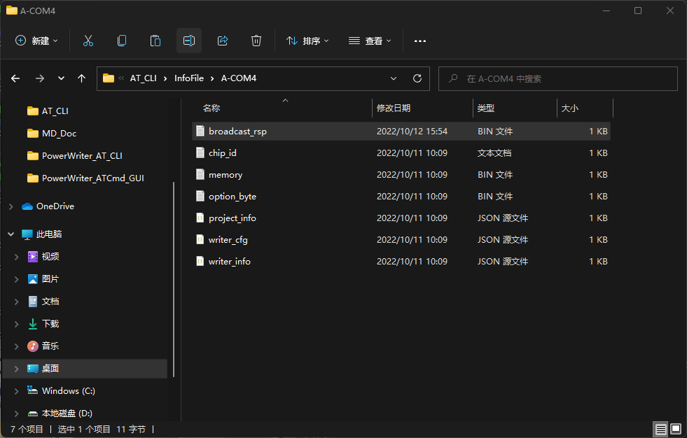
4. Files generated by the "get command"
- The "Query PW Information" file is generated as :writer_info.json
- The "Query PW Configuration" generates a file as: writer_cfg.json
- "Get Target Chip ID" generates the file: chip_id.txt.
- The file "Read target chip data" is generated as: memory.bin.
- "Read target chip option word" generates the file: option_byte.bin
- "Query offline project information" generates the file: project_info.json"
- "Broadcast Response Data" generates the file: broadcast_rsp.bin."
As shown in figure 1.3.1 below
5 AT Script File Content Format
AT Command Code Command Parameter 1 Parameter Value 1 Command Parameter 2 Parameter Value 2
5.1 AT Command Code Description
"-info": Query PW information
"-cfg":Query PW Configuration
"-setcfg {-f *.json}":Update PW information
"-setbaud {-b}":Setting the AT interface baud rate
"-reset -type": reset target
"-connect":Connecting the target chip
"-status":Get target chip connection status
"-cid":Get target chip ID
"-read {-addr -s}":Read target chip data
"-erase {-t}":Erase Target Chip
"-erase {-t -addr -s}":Erase Target Chip Sector
"-write" {-addr -f *.bin}:Write target chip data
"-read-ob":Read target chip option byte
"-write-vob {-t}":Write target chip default option byte
"-write-uob {-t}":Write target chip user option byte
"-prj-info":Check offline project information
"-prj-ld {-f *.pkg} [-pwd]": Loading offline projects
"-prj-dis":Disable offline projects
"-start":Start offline programming
"-offline-status":Query offline programming status
"-factory-sram-fw":Running FactoryTest SRAM Firmware
"-factory-flash-fw":Run FactoryTest Flash Firmware
"-bcst {-data} | {-f *.txt|*.bin} [-dir] [-kf] [-wtrsp -t]":Extended Command-Broadcasting
"-sleep {-t}":Sleep
5.2 AT Command Parameter Description
"-f":Specify the path and filename of the file to be read
"-pwd":Enter the project password
"-b":Setting the baudrate
"-type": Set reset type, 0~6, default is 3,refer to https://docs.powerwriter.com/en/docs/next/powerwriter_for_arm/reference/ATCommand#ATCmdTargetReset
"-addr":Set address (10, hex)
"-s":Set data size (10, hexadecimal)
"-t":timeout
"-data":Setting Immediate Data
"-dir":Set the broadcast direction:"usbtouart/uarttousb"
"-kf":Whether to forward the complete AT frame structure:"true/false"
"-wtrsp":Whether to wait for a broadcast answer: "true/false"
"-fw-num":Hex file firmware serial number, 0 is the starting serial number, all burn parameters are "all".
6 Error code
- 0.Unknown error ...
- 1.The package crc validation failure...
- 2.The writer product oem does not match...
- 3.The writer is busy now...
- 4.The writer is in use...
- 5.The writer communication handle error...
- 6.The writer configuration error...
- 7.The target flash algorithm config error...
- 8.The target option byte config error...
- 9.The target chip is not connected...
- 10.The target erase failed...
- 11.The target write data failed...
- 12.The target read data failed...
- 13.The package timeout error...
- 14.The extends flash initial failed...
- 15.The extends flash erase failed...
- 16.The extends flash write failed...
- 17.The extends flash verify failed...
- 18.The extends flash read failed...
- 19.The package size error...
- 20.The target chip type error...
- 21.The target read unique id failed...
- 22.The writer update firmware failed...
- 23.The target chip protection is enabled...
- 24.The target write flash failed...
- 25.The target write option byte failed...
- 26.The writer SN error or don't match...
- 27.The target write matrix license failed...
- 28.The target write ICWKEY license failed...
- 29.The project matrix license version error...
- 30.The ICWKEY failed to request a signature...
- 31.The project of offline times has used up...
- 32.The project of version error...
- 33.The project of oem error...
- 34.The project of magic tag error...
- 35.The project of data corruption...
- 36 .The project disabled...
- 37.The package size error...
- 38.The communication port error...
- 39.The communication package error...
- 40.The writer needs to be disconnected from the online connection....
- 41.The communication port send package error...
- 42.The communication port waiting response time out...
- 43.The command is unsupported ...
- 44.The config is(has) null value ...
- 45.The target flash algorithm config error...
- 46.The Incorrect authentication password...
- 47.Disconnect the device and power it on again to complete the upgrade...
- 48.The extends ICWKEY device is not connect...
- 49.The voltage error (abnormal power supply)...
- 50.The debugger is connected...
- 51.The wireless is connecting...
- 52.The serial port check failed...
- 53.The I/O check failed...
- 54.The button check failed...
- 55.The wireless check failed...
- 56.The writer memory error...
- 57.The writer sn is limited ...
- 58.The target unique ID is limited...
- 59.The project file version is too low, please repackage...
- 60.Please connect PowerWriter device first...
- 61.The target FT(CP) validation fails ...
- 62.The target password error(such as KPROM)...
- 63.The target SPI flash not connected(such as NUVOTON) ...
- 64.The target abnormal access detected...
- 65.The target write KPROM failed...
- 66.The target write XOM failed...
- 67.The target write secure setting failed...
- 68.The target write MTP failed...
- 69.The FUS not running ...
- 70.The stack not running ...
- 71.The FUS upgrade error ...
- 72.The stack upgrade error ...
- 73.The FUS state image not found...
- 74.The FUS state image corrupt...
- 75.The FUS state image not authentic...
- 76.The FUS state image not enough space...
- 77.The FUS state user abort...
- 78.The FUS state erase error...
- 79.The FUS state write error...
- 80.The FUS ST authorization tag was not found...
- 81.The FUS custom authorization tag was not found...
- 82.The FUS authorization key locked...
- 83.The FUS UFB corrupt...
- 84.The FUS state other error ...
- 85.The stack type error ...
- 86.The vendor signature is too long
- 87.The vendor signature data is corrupted
- 88.The current target chip has no signature
- 89.Factory test disabled...
- 90.Factory test have no sram firmware...
- 91.Factory test have no flash firmware...
- 92.Write data to target SRAM failed...
- 93.Current baudrate not supported...
- 94.AT Command broadcast direction error ...
- 95.Need keep AT full frame to current receive port...
- 96.The super serial number configuration data is abnormal...
- 97.The super serial number has no remaining data...
- 98.Failed to write the super serial number...
- 99.The firmware loader digest no match...
- 100.Load DFU failed...
- 101.Update firmware(modem) failed...
- 102.Verify failed...
- 103.Reset target chip failed ...
- 104.This target chip has failed to handle boot loader...
Error codes not listed are reserved.
7 CLI Command Line
7.1 Command line without parameters
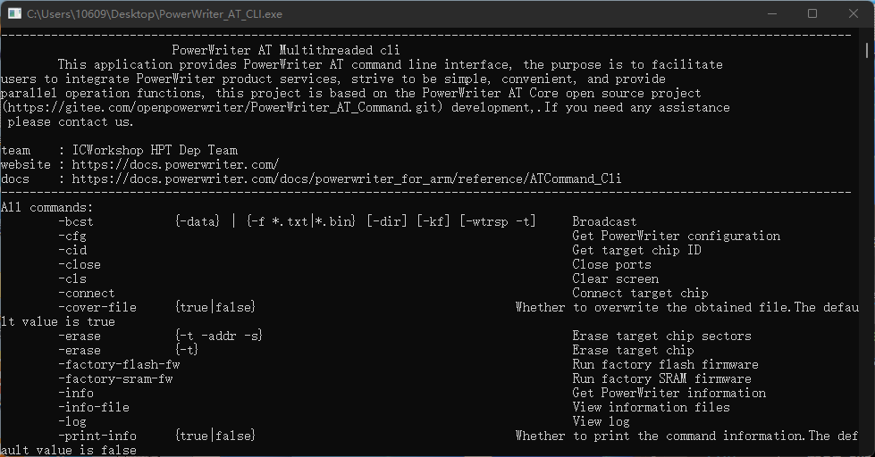
Run the command line software directly, it will print the description and help document of the software, as shown in Fig. 2.1 and Fig. 2.1-2, "PowerWriter® AT command" is the name of the command software, and you can input commands after ">". Note: Before executing all AT commands, you need to execute the "-scan" command to scan the PowerWriter® with AT function enabled.

7.2 Command with parameters
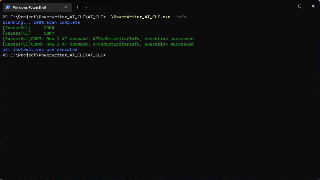
The parameter can be an AT command code, or . \ AT script file, the programmer will automatically execute the "-scan" command, and then execute the input parameter command, the command execution is complete, the end of the program. As shown in Figure 2.2 and Figure 2.3 below:

7.3 Command line software commands
7.3.1 All AT script commands
See 1.4 AT Script File Content Format for details.
7.3.2 Special CMD
"-scan": scanning PowerWriter with AT enabled
"-close": disconnect all PowerWriter connections
"-cls": clears the contents of the screen
"-q": exit the application
"-print-info {true|false}": whether to print the information obtained by the get command.
"-cover-file {true|false}": whether or not to cover the information file obtained by the get command
"-info-file": opens the folder "Get the information file obtained by the command".
"-log": open log folder
". *.patscript": execution of AT script file
"-h": help
7.3.3 Special note
Tab key can complete the command, input ". +folder" and press Tab key to complete the .patscript file directly, if the script file is in the software directory, type ". If the script file is in the software directory, type ". \" and press Tab key to complete the .patscript file directly.
With the -f parameter entered, the Tab key completes the file.
String arguments can be unquoted, e.g. -f "sample_files\test.bin" can be written as -f sample_files\test.bin. Without quotes, the parsing command is terminated by a space.
7.4 Return value
0: Execution successful, no errors
1~24: Number of errors in PowerWriter execution commands
1000: No PowerWriter scanned
1001: parameter file (target file for -f) is not in json file format
1002: parameter file (target file of -f) is not in bin file format
1003: parameter file (target file for -f) is not in pkg file format
1004: parameter file (target file for -f) not in txt file format
1005: Baud rate less than or equal to 0
1006: time out less than or equal to 0
1007: parameter file (target file for -f) does not exist
1008: parameter file (target file for -f) is empty
1009: json file data error (missing key)
1010: start address less than or equal to 0
1011: Data size less than or equal to 0
1012: Invalid string command parameter (valid string parameters are true, false, uarttousb, usbtouart)
2001: Duplication of orders
2002: Invalid order
2003: Duplicate command parameters
2004: Command parameter dichotomy, 2 choose 1 parameter, both parameters appearing
2005: Too many command parameters
2006: File format error
2007: Document does not exist